Flue gas purification method

A flue gas purification and flue gas technology, which is applied in the field of flue gas purification, can solve the problems of large wind resistance and low liquid-gas ratio of the Venturi tube, and achieve the effects of high liquid-gas ratio, large spray water volume, and moderate wind resistance

Inactive Publication Date: 2021-02-26
SICHUAN LANDE IND
View PDF3 Cites 0 Cited by
  • Summary
  • Abstract
  • Description
  • Claims
  • Application Information

AI Technical Summary

Problems solved by technology

[0004] The purpose of the present invention is to provide a flue gas purification method to solve the problems of the existing Venturi tube with large wind resistance and low liquid-gas ratio during flue gas treatment

Method used


Image

  • Flue gas purification method

Examples


Embodiment 1

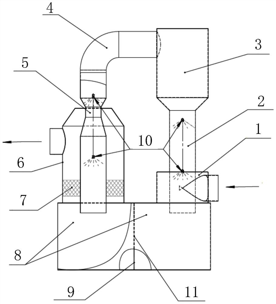
[0037] like figure 1 Shown, a kind of flue gas purification method comprises the following steps:

[0038] S1. Lead the flue gas from the air inlet pipe into the cyclone dust collection section 1 to remove large particles in the flue gas;

[0039] S2. The pretreatment section 2 where the flue gas after removing the large particles goes upwards, uses the nozzle 10 to spray the flue gas to cool down, remove acid and remove small particles, and the wind speed of the pretreatment section 2 is controlled at 8-12m / s;

[0040] S3. The pretreated flue gas enters the dehydration section 3 upwards for water droplet settlement treatment, and the wind speed of the dehydration section 3 is less than or equal to 4m / s;

[0041] S4. The flue gas that has been treated by water droplet settlement enters the purification section 5 downwards for spray purification treatment, and the wind speed of the purification section 5 is controlled at 20-30m / s;

[0042] S5. The flue gas that has been spray...

Embodiment 2

[0050] like figure 1 As shown, this embodiment is based on Embodiment 1, and the purification section 5 includes an upper connection section, a middle section and a lower connection section, the upper connection section is connected to the air duct 4, and the two ends of the middle section are respectively connected to the upper section is connected with the lower connecting section, the lower connecting section communicates with the water tank 8, the inner diameter of the middle section is smaller than the inner diameter of the upper connecting section, the nozzle 10 is arranged at the entrance of the middle section, and the upper connecting section and the lower connecting section are connected The sections have the same inner diameter, and a spray head 10 is arranged in the lower connecting section.

[0051] In this embodiment, a throat is formed on the purification section 5. After the flue gas enters the purification section 5, the throat is formed due to the sudden reduc...

Embodiment 3

[0053] The lower end of the pretreatment section 2 extends into the water tank 8 through the cyclone dust collection section 1 .


PUM


Abstract

The invention discloses a flue gas purification method which comprises the following steps that: S1, flue gas is introduced into a cyclone dust collection section from an air inlet pipe to remove large particulate matters in the flue gas; S2, the flue gas with the large particles removed upwards enters a pretreatment section, a spray head is adopted for spraying the flue gas for cooling, deacidifying and removing small particles, and the air speed of the pretreatment section is controlled to be 8-12 m / s; S3, the pretreated flue gas upwards enters a dehydration section for water drop sedimentation treatment, and the air speed of the dehydration section is smaller than or equal to 4 m / s; S4, the flue gas subjected to water drop sedimentation treatment downwards enters a purification sectionfor spraying purification treatment, and the air speed of the purification section is controlled to be 20-30 m / s; and S5, the flue gas subjected to spray purification treatment enters a demisting tower to remove water mist in the flue gas, and the flue gas is discharged through an air outlet pipe. The problem that an existing venturi tube is large in wind resistance and low in liquid-gas ratio during flue gas treatment is solved.

Description

technical field [0001] The invention relates to the technical field of flue gas treatment, in particular to a method for purifying flue gas. Background technique [0002] For the treatment of high-temperature and high-concentration acid flue gas, wet dust removal equipment such as scrubbers and venturi tubes are usually used, but they all have different scopes of application. For example, the advantages of scrubbers are large flue gas treatment capacity and low wind speed (3 ~4m / s) small wind resistance (the total pressure of the fan is usually lower than 2000Pa), the disadvantages are low water spray density, low efficiency of dust removal and acid removal, and it is difficult for the flue gas to meet the emission standards; while the advantages of the venturi tube are just the opposite, its main The advantage is that the efficiency of dust removal and acid removal is high, but the disadvantage is that high wind speed (40-120m / s) is used to improve the treatment efficiency,...

Claims


Application Information

Patent Timeline
IPC IPC(8): B01D50/00B01D47/06B01D53/14
CPCB01D50/00B01D47/06B01D53/1456B01D2258/0283B01D50/40
Inventor 袁名万欧福广
Owner SICHUAN LANDE IND
Why Eureka
Try Eureka