


Quick Research
Generate reliable direction feasibility study reports for your R&D in just a few steps.

Technical Q&A
Discover and master advanced knowledge NOW. Basics, ideas, possibilities, all at once.

Find Solutions
As an expert in R&D theories, this can generate solutions to your technical problems instantly.

Evaluate Feasibility
Analyze your overall solution with one click, know your potential R&D risks in advance.

Monitor Landscape
Get weekly tech updates, stay abreast of the latest tech innovations and key insights.
Piezoelectric element detection system and method and application
A piezoelectric element and detection system technology, applied in the field of detection, can solve the problems of piezoelectric cantilever beams that cannot be fed back in time, engineering failures, poor driving effects, etc.
- Summary
- Abstract
- Description
- Claims
- Application Information
AI Technical Summary
Problems solved by technology
Method used
Image

Examples
Embodiment 1
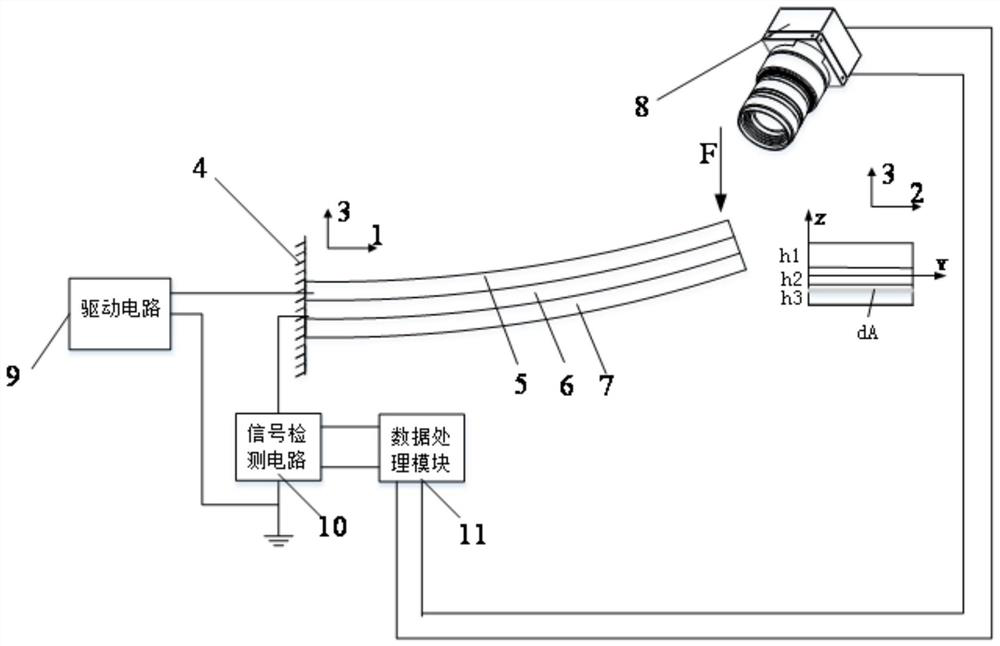
[0072] A piezoelectric element detection system, such as figure 1 As shown, it includes: a drive circuit 9, a piezoelectric element 4, a signal detection circuit 10 and a data processing module 11 connected in sequence; the data processing module 11 is used to calculate the actual output current value of the piezoelectric element 4, and convert the piezoelectric The actual output current value of the element 4 is compared with the output current threshold when the piezoelectric element 4 is in normal working state, and it is judged whether the piezoelectric element 4 is in an abnormal working state.
[0073] The driving circuit 9 is used to transmit electric energy to the piezoelectric element 4 to realize the electrical open circuit and electrical short circuit of the piezoelectric element 4, and provide different electrical boundary conditions for the piezoelectric element 4. According to different application occasions of the piezoelectric element 4, the piezoelectric The m...
Embodiment 2
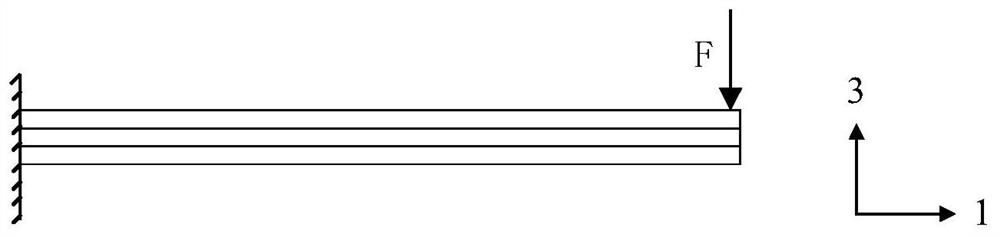
[0083] A piezoelectric element detection method, according to a piezoelectric element detection system described in any one of the technical solutions in Embodiment 1, comprising: setting the mechanical boundary conditions of the piezoelectric element 4, and setting the piezoelectric element through the drive circuit 9 4. Set the electrical boundary conditions; the output signal of the piezoelectric element 4 is sent to the data processing module 11 for processing through the signal detection circuit 10, and the actual output current value of the piezoelectric element 4 is calculated; the actual output current value of the piezoelectric element 4, Compared with the output current threshold value of the piezoelectric element 4 under the set mechanical boundary conditions and electrical boundary conditions when the working state is normal, it is judged whether the working state of the piezoelectric element 4 is abnormal.
[0084]Under different electrical boundary conditions and ...
PUM
 Abstract
Description
Claims
Application Information
 - R&D Engineer
- R&D Manager
- IP Professional
- Industry Leading Data Capabilities
- Powerful AI technology
- Patent DNA Extraction
Browse by: Latest US Patents, China's latest patents, Technical Efficacy Thesaurus, Application Domain, Technology Topic, Popular Technical Reports.
© 2024 PatSnap. All rights reserved.Legal|Privacy policy|Modern Slavery Act Transparency Statement|Sitemap|About US| Contact US: help@patsnap.com