
Unmanned vehicle laser anti-sniping system and anti-sniping control method thereof

A control method and laser emission system technology, applied in the anti-sniper system and its anti-sniper control field, can solve the problems of casualties and other problems, and achieve the effects of reducing casualties, long search distance, and rapid mobile deployment

Pending Publication Date: 2021-02-23
合肥正阳光电科技有限责任公司
View PDF0 Cites 2 Cited by
  • Summary
  • Abstract
  • Description
  • Claims
  • Application Information

AI Technical Summary

Problems solved by technology

However, most of the anti-sniper systems are passive detection. Although the position of the sniper can be accurately detected to realize the anti-sniper, it can only be discovered after the sniper fires the first shot. casualties

Method used


Image

  • Unmanned vehicle laser anti-sniping system and anti-sniping control method thereof
  • Unmanned vehicle laser anti-sniping system and anti-sniping control method thereof

Examples

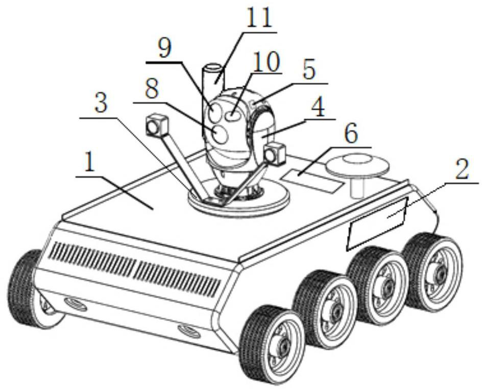
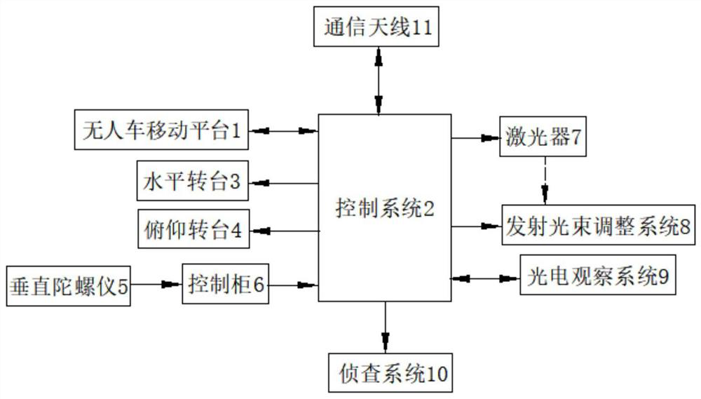

Embodiment Construction

[0023] The following will clearly and completely describe the technical solutions in the embodiments of the present invention with reference to the accompanying drawings in the embodiments of the present invention. Obviously, the described embodiments are only some, not all, embodiments of the present invention. Based on the embodiments of the present invention, all other embodiments obtained by persons of ordinary skill in the art without making creative efforts belong to the protection scope of the present invention.

[0024] See figure 1 and figure 2 , an unmanned vehicle laser anti-sniper system, including an unmanned vehicle mobile platform 1, a control system 2 set on the unmanned vehicle mobile platform 1, a two-axis servo turntable, a laser emission system and a sighting system; the unmanned vehicle mobile platform 1 is a semi-autonomous remote control unmanned vehicle, which detects road conditions through terrain detection sensors, and feeds back road condition inf...


PUM


Abstract

The invention discloses an unmanned vehicle laser anti-sniping system and an anti-sniping control system thereof. The unmanned vehicle laser anti-sniping system comprises an unmanned vehicle moving platform, a control system arranged on the unmanned vehicle moving platform, a two-axis servo rotary table, a laser emitting system and an observing and aiming system. The laser emitting system and theobserving and aiming system are both arranged on the two-axis servo rotary table, and the observing and aiming system, the two-axis servo rotary table, the laser emitting system and the unmanned vehicle moving platform are all connected with the control system. According to the unmanned vehicle laser anti-sniping system, autonomous rear remote control maneuvering deployment is achieved through anunmanned vehicle-mounted mobile platform, real-time adjustment can be conducted according to the requirement of the field environment, countering of a sniper is achieved through visible lasers and infrared lasers, casualties caused by sniping countering are reduced in the complex battlefield environment, and sniping countering under the maneuvering deployment condition of an unmanned vehicle is achieved.

Description

technical field [0001] The invention relates to the field of optoelectronic technology, in particular to an anti-sniper system and an anti-sniper control method for urban operations, anti-terrorism, and security. Background technique [0002] A sniper is a member of the armed forces responsible for a covert ambush. In a complex battlefield environment, enemy snipers use their own equipment to carry out long-distance harassment and reconnaissance, which poses a huge threat. At this time, counter-sniping has become an important means of resistance. In the process of counter-sniping, it is necessary to have the ability to maneuver, reconnaissance, countermeasures and reduce casualties. However, most of the anti-sniper systems are passive detection. Although the position of the sniper can be accurately detected to realize the anti-sniper, it can only be discovered after the sniper fires the first shot. casualties. Contents of the invention [0003] The technical problem to ...

Claims


Application Information

Patent Timeline
Patent Type & Authority Applications(China)
IPC IPC(8): F41H11/00G01D21/02
CPCF41H11/00G01D21/02
Inventor 王培飞张继前胡明君疏义乐李飞费腾杨凯胡浩
Owner 合肥正阳光电科技有限责任公司
Learn More