


Quick Research
Generate reliable direction feasibility study reports for your R&D in just a few steps.

Technical Q&A
Discover and master advanced knowledge NOW. Basics, ideas, possibilities, all at once.

Find Solutions
As an expert in R&D theories, this can generate solutions to your technical problems instantly.

Evaluate Feasibility
Analyze your overall solution with one click, know your potential R&D risks in advance.

Monitor Landscape
Get weekly tech updates, stay abreast of the latest tech innovations and key insights.
Self-adaptive structure capable of self-adapting to size of embedded hole and embedded cooker
A self-adaptive and dimensional technology, applied in the field of cookers, can solve the problems of complicated installation and the inability to completely eliminate the risk of scratching the cabinets with shaking gaps, and achieve the effect of strong self-adaptation
- Summary
- Abstract
- Description
- Claims
- Application Information
AI Technical Summary
Problems solved by technology
Method used
Image


Examples
Embodiment 1
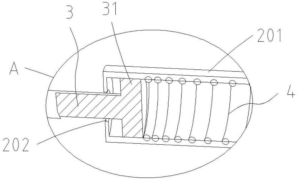
[0033] Referring to 1-4, this embodiment provides an adaptive structure that can adapt to the size of the embedded hole. The adaptive structure includes a pressure member 1, a bracket 2, a pull rod 3, an elastic member 4 and at least one traction member 7, Wherein the pressure bearing part 1 is used to abut against the inner side wall of the embedded hole. The bracket 2 is used to connect with the bottom shell of the cooker, and the bracket 2 is provided with a mounting column extending toward the direction of the pressure-bearing part 1 and arranged laterally, and an installation cavity 201 is defined inside the mounting column, and the mounting column faces the pressure-bearing part 1 A hole 202 is provided on one side, the hole 202 faces the pressure bearing part 1 and communicates with the installation cavity 201 . One end of the pull rod 3 is telescopically and movably arranged in the installation cavity 201, and the other end passes through the opening 202 to hinge the p...
Embodiment 2
[0053] see Figure 8 , The difference between this embodiment and Embodiment 1 is that the structure of the bracket 2 is different. Specifically, the bracket 2 includes a bottom surface 22 and two support surfaces 23, the lower ends of the two support surfaces 23 are respectively integrally formed with the bottom surface 22, and the upper side of each support surface 23 is provided with a mounting column extending toward the direction of the pressure bearing 1. , the mounting column has a mounting cavity 201 and an opening 202 communicating with the mounting cavity 201 . In addition, a pulling member 7 for pulling the pressure-bearing member 1 is fixedly connected to the lower side of each supporting surface 23 by welding. Two fixing holes 203 are provided on the bottom surface 22. When the self-adaptive structure is installed on the bottom shell of the cooker, two screws can pass through the two fixing holes 203 respectively and then be detachably connected with the bottom s...
Embodiment 3
[0056] see Figure 9-10 , The difference between this embodiment and Embodiment 1 is that the structure of the bracket 2 is different. Specifically, the bracket 2 includes a bottom surface 22 and a support surface 23, the bottom surface 22 and the support surface 23 are integrally formed and form an "L" shape with each other, and two fixing holes 203 are provided on the bottom surface 22. There are two mounting posts extending toward the pressure bearing part 1 , each mounting post has a mounting cavity 201 and an opening 202 communicating with the mounting cavity 201 .
[0057]Specifically, the number of the traction member 7 is one, and the lower side of the pressure bearing member 1 facing the support surface 23 is provided with a connecting seat 13 with a hook hole, and the connecting seat 13 is located below the connecting line of the two supports 11 . The lower side of the support surface 23 is provided with a connecting seat 13 located below the line connecting the two...
PUM
 Abstract
Description
Claims
Application Information
 - R&D Engineer
- R&D Manager
- IP Professional
- Industry Leading Data Capabilities
- Powerful AI technology
- Patent DNA Extraction
Browse by: Latest US Patents, China's latest patents, Technical Efficacy Thesaurus, Application Domain, Technology Topic, Popular Technical Reports.
© 2024 PatSnap. All rights reserved.Legal|Privacy policy|Modern Slavery Act Transparency Statement|Sitemap|About US| Contact US: help@patsnap.com