Shifting fork clutch structure of industrial gantry crane reduction gearbox

A technology of gear box and industrial door, which is applied in the direction of controlled components, mechanical equipment, mechanical control devices, etc. It can solve the problems of large clutch volume of industrial door machine gear box and no clutch of industrial door machine gear box, so as to increase the number of application scenarios and the effect of ease of use

Inactive Publication Date: 2021-02-23
无锡弗斯门控科技有限公司
View PDF1 Cites 0 Cited by
  • Summary
  • Abstract
  • Description
  • Claims
  • Application Information

AI Technical Summary

Problems solved by technology

[0005] One object of the present invention is to provide a fork clutch reducer, which has the advantages of solving the problem of no clutch in the reduction box of industrial door machine and solving the problem of excessive clutch volume of the reduction box of industrial door machine

Method used


Image

  • Shifting fork clutch structure of industrial gantry crane reduction gearbox
  • Shifting fork clutch structure of industrial gantry crane reduction gearbox
  • Shifting fork clutch structure of industrial gantry crane reduction gearbox

Examples


Embodiment Construction

[0016]The specific embodiments of the present invention will be further described below in conjunction with the drawings.

[0017]The technical scheme adopted by the present invention is:

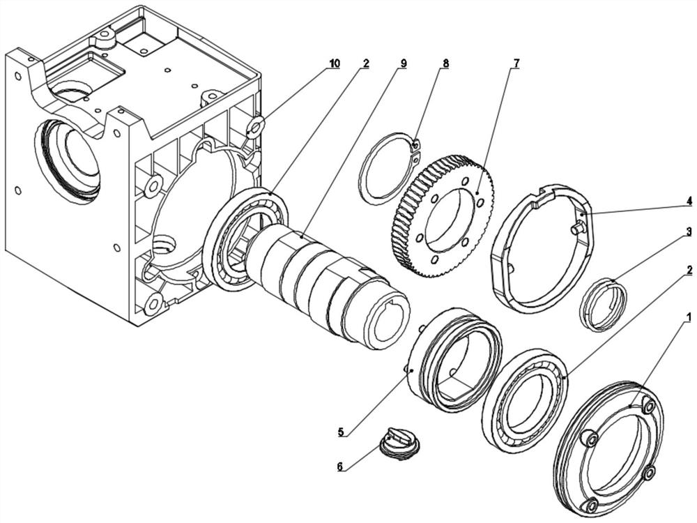
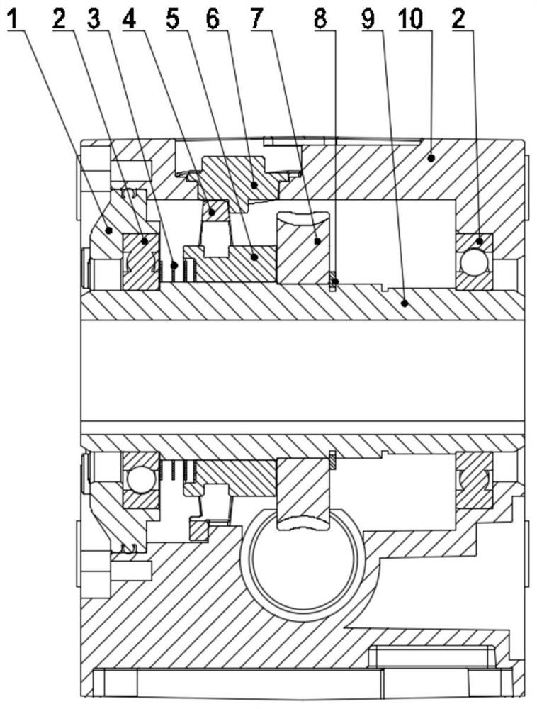
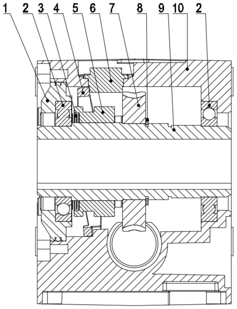
[0018]A shift fork clutch structure of industrial door machine gearbox, such asfigure 1 ,figure 2 andimage 3As shown, the reduction box 10 is included. The reduction box 10 is provided with an output shaft 9 rotatably connected with the reduction box 10, and the top of the output shaft 9 is also provided with a reduction box cover 1 matching the reduction box 10, and the output shaft 9 is close to the reduction box cover One side of 1 is also covered with a wave spring 3, while the output shaft 9 is also covered with a sliding key 5, and the wave spring 3 is stuck on the inner wall of the sliding key 5, and the wave spring 3 is also provided with a shift fork 4, and the shift fork There is a cam 6 on one side of 4, a worm wheel 7 on the side of the feather key 5 on the output shaft 9, a circlip 8 on th...


PUM


Abstract

The invention discloses a shifting fork clutch structure of an industrial gantry crane reduction gearbox, and aims to provide a shifting fork clutch structure used by an industrial gantry crane. The shifting fork clutch structure is characterized by comprising the reduction gearbox, wherein an output shaft rotatably connected with the reduction gearbox is arranged in the reduction gearbox, a wavespring is sleeved on one side of the output shaft, the output shaft is further sleeved with a sliding key, the wave spring is clamped on the inner wall of the sliding key, a shifting fork is further arranged on the wave spring, a cam is arranged on one side of the shifting fork, a worm gear is further arranged on the output shaft and located on one side of the sliding key, and a clamping spring isfurther arranged on one side of the worm gear.

Description

Technical field[0001]The invention relates to the field of industrial door equipment, in particular to a shift fork clutch structure of an industrial door machine gear box.Background technique[0002]The shift fork is a component on the automobile gearbox. It is connected to the shift handle and is located at the lower end of the handle. The middle shift wheel is moved to change the input / output speed ratio. The shift fork is mainly used for clutch shifting. If it is a shift fork on a machine tool, it is Used for speed change, mainly used in the control mechanism is to pull apart the two meshing gears and then one of the gears that can slide on the shaft to the other gear to obtain another speed, that is, to change the sliding gear of the lathe The position of, to achieve variable speed, or used in the mechanism of controlling the engagement and disengagement of the clutch, so as to control the transverse or longitudinal feed.[0003]At present, the Chinese patent with publication numbe...

Claims


Application Information

Patent Timeline
Patent Type & Authority Applications(China)
IPC IPC(8): F16H63/32F16H57/023F16H57/021F16H57/031F16H57/032F16H53/02F16H55/22
CPCF16H53/025F16H55/22F16H57/021F16H57/023F16H57/031F16H57/032F16H63/32
Inventor 梁小健姜兴隆
Owner 无锡弗斯门控科技有限公司
Why Eureka
Try Eureka