Fire-fighting aerial ladder

A fire-fighting aerial ladder and ladder frame technology, which is applied to the layout of ladders and wings, buildings, etc., can solve the problems of limited working bucket space, reduced rescue efficiency, and slow rescue speed of fire-fighting aerial ladders, so as to prevent personnel injuries and improve efficiency , the effect of improving safety

Inactive Publication Date: 2021-02-23
牛泊雄
View PDF9 Cites 1 Cited by
  • Summary
  • Abstract
  • Description
  • Claims
  • Application Information

AI Technical Summary

Problems solved by technology

[0003] When the existing aerial ladder fire truck is in use, when it is necessary to rescue people at high altitude, due to the limited space of the working bucket of the fire fighting aerial ladder, when the working bucket is full, it needs to be lowered to unload the personnel to carry out the next rescue, and the lifting process back and forth It leads to the reduction of rescue efficiency and slow rescue speed.

Method used


Image

  • Fire-fighting aerial ladder
  • Fire-fighting aerial ladder
  • Fire-fighting aerial ladder

Examples


Embodiment 1

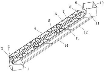
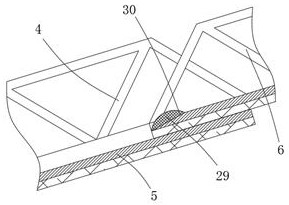
[0031] refer to Figure 1-4 , a fire-fighting aerial ladder, comprising a base 1 and a working bucket 11, a first ladder frame 6 is rotatably connected to one side of the bottom outer wall of the working bucket 11, and at least two sliding connections are provided between the first ladder frame 6 and the base 1 An integrated second ladder frame 4, the first ladder frame 6 is slidably connected to the side inner wall of the uppermost second ladder frame 4, the bottom end of the lowermost second ladder frame 4 is rotatably connected to the top outer wall of the base 1, the first Both the bottom inner wall of the ladder frame 6 and the second ladder frame 4 are laid with a slide plate 5, and the bottom end of the lowermost second ladder frame 4 is fixedly connected with a baffle plate 2, and the baffle plate 2 is fixed toward the side outer wall of the second ladder frame 4 Connected with a buffer air cushion 3, the side outer wall of the working bucket 11 away from the first lad...

Embodiment 2

[0042] refer to Figure 5 , a fire ladder. Compared with Embodiment 1, this embodiment replaces the first support arm 12 with an adjustment arm 15, and the adjustment arm 15 includes a third support arm 16, an adjustment hydraulic rod 17, a connecting shell 18, a fourth Support arm 19, slider 21 and slide rail 20, the third support arm 16 is slidably connected to the side inner wall of the second support arm 14, the connecting shell 18 is slidably connected to the side outer wall of the third support arm 16, and the adjustment hydraulic rod 17 is fixedly connected Between the outer wall of one end of the third support arm 16 and the inner wall of one end of the connecting shell 18, the fourth supporting arm 19 is fixedly connected to the outer wall of one end of the connecting shell 18, and the slider 21 is rotatably connected to the outer wall of one end of the fourth supporting arm 19. The rail 20 is fixedly connected to the bottom outer wall of the working bucket 11 , and t...


PUM


Abstract

The invention belongs to the technical field of fire-fighting equipment, and particularly relates to a fire-fighting aerial ladder. For solving the problems in the prior art, the following scheme is and provided that the fire-fighting aerial ladder comprises a base and a working bucket, a first ladder frame is rotatably connected to one side of the outer wall of the bottom of the working bucket, at least two second ladder frames which are slidably connected into a whole are arranged between the first ladder frame and the base, the first ladder frame is slidably connected to the inner wall of the side face of the uppermost second ladder frame, the bottom end of the lowermost second ladder frame is rotatably connected to the outer wall of the top of the base, sliding plates are laid on the inner walls of the bottoms of the first ladder frame and the second ladder frame, and a baffle is fixedly connected to the bottom end of the lowermost second ladder frame. According to the fire-fighting aerial ladder, rescue efficiency is improved, a buffer air cushion can achieve a buffer effect, then personnel can be prevented from being injured, the situation that the personnel slide down too fast and are injured can be prevented, the speed of the personnel sliding to the bottom end can be reduced, safety is further improved, and the working bucket can be kept in a horizontal state all the time.

Description

technical field [0001] The invention relates to the technical field of fire-fighting equipment, in particular to a fire-fighting aerial ladder. Background technique [0002] The aerial ladder fire truck is equipped with a hydraulic lifting platform for firefighters to climb up and fight fires in high-rise buildings, tall facilities, oil tanks, etc., rescue trapped people, rescue valuable materials and complete other rescue tasks. There is a telescopic aerial ladder on the car. Equipped with lift bucket turntable and fire extinguishing device, it is used for firefighters to ascend to put out fires and rescue trapped people, and is suitable for fighting fires in high-rise buildings. [0003] When the existing aerial ladder fire truck is in use, when it is necessary to rescue people at high altitude, due to the limited space of the working bucket of the fire fighting aerial ladder, when the working bucket is full, it needs to be lowered to unload the personnel to carry out the ...

Claims


Application Information

Patent Timeline
Patent Type & Authority Applications(China)
IPC IPC(8): E06C5/04E06C5/32E06C7/16E06B3/50
CPCE06C5/04E06C5/32E06C7/16E06B3/50
Inventor 牛泊雄
Owner 牛泊雄
Why Eureka
Try Eureka