
Engine rotor and stator structure assembling and disassembling device

A technology for rotating stators and engines, which is applied to engine components, machines/engines, workpiece clamping devices, etc., and can solve problems such as blade damage, slipping, and collapse of the bleed air system.

Active Publication Date: 2021-02-23
AECC SHENYANG ENGINE RES INST
View PDF6 Cites 2 Cited by
  • Summary
  • Abstract
  • Description
  • Claims
  • Application Information

AI Technical Summary

Problems solved by technology

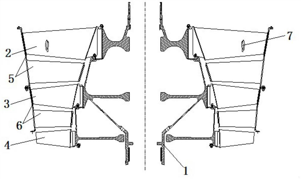
[0004] When disassembling the rotor-stator structure of the above-mentioned engine, it is mostly fixed vertically by the support mechanism, and at the same time it is axially positioned and radially centered. This kind of scheme can easily realize the rotor hub assembly 1, The disassembly and assembly of the second-stage rotor blade 3, the third-stage rotor blade 4, the first-stage stator case 5 with guide vanes, and the second-stage stator case 6 with guide vanes, but when disassembling the first-stage rotor blade 2, Since the installation mortise of the first-stage rotor blade 2 on the rotor hub assembly 1 is inclined at a certain angle to the axis of rotation, and the first-stage rotor blades 2 are overlapped by shoulders 7 , during the disassembly process, the coupling Interference will easily cause the blade to slip from the installation tenon and groove, the bleed air will collapse systematically, and friction will occur, which will cause the shoulder 7 to tear or be damaged by falling pieces, resulting in damage to the blade

Method used


Image

  • Engine rotor and stator structure assembling and disassembling device
  • Engine rotor and stator structure assembling and disassembling device
  • Engine rotor and stator structure assembling and disassembling device

Examples


Embodiment Construction

[0056] In order to make the technical solution of the present application and its advantages clearer, the technical solution of the present application will be further clearly and completely described in detail below in conjunction with the accompanying drawings. It can be understood that the specific embodiments described here are only part of the application Examples are only used to explain the present application, not to limit the present application. It should be noted that, for the convenience of description, only the parts related to the present application are shown in the drawings, and other relevant parts can refer to the general design. In the case of no conflict, the embodiments in the application and the technologies in the embodiments Features can be combined with each other to obtain new embodiments.

[0057] In addition, unless otherwise defined, the technical terms or scientific terms used in the description of the application shall have the usual meanings und...


PUM


Abstract

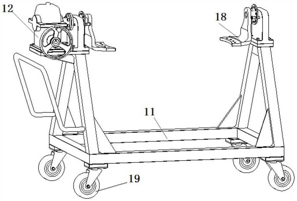
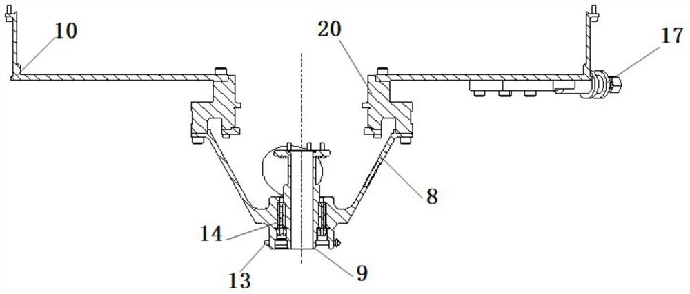
The invention belongs to the technical field of disassembly and assembly design of an engine rotor and stator structure, and particularly relates to an engine rotor and stator structure assembling anddisassembling device. The engine rotor and stator structure assembling and disassembling device comprises a support seat, a positioning shaft, a positioning cylinder, a support and a rotating device,wherein one end of the positioning shaft is connected with the support seat, one end of the positioning cylinder is connected with the support seat, the positioning cylinder and the positioning shaftare coaxially arranged, and the rotating device is arranged on the support and is connected with the support seat or the positioning cylinder so as to drive the positioning cylinder and the positioning shaft to turn over.

Description

technical field [0001] The application belongs to the technical field of disassembly and assembly design of an engine rotor-stator structure, and in particular relates to a disassembly and assembly device for an engine rotor-stator structure. Background technique [0002] The stator structure of a turbofan engine with a small bypass ratio includes a rotor hub assembly 1, a first-stage rotor blade 2, a second-stage rotor blade 3, a third-stage rotor blade 4, a first-stage stator casing with guide vanes 5, and a first-stage stator casing with guide vanes. The secondary stator casing 6, such as figure 1 shown. [0003] Considering the ease of disassembly and assembly of the engine rotor-stator structure, the assembly sequence of the above-mentioned engine rotor-stator structure is designed as follows: three-rotor hub assembly 1→secondary stator case 6 with guide vanes→secondary rotor blade 3→with guide vanes The first-stage stator casing 5 → the third-stage rotor blade 4 → th...

Claims


Application Information

Patent Timeline
IPC IPC(8): B25B11/02B25H1/06F01D25/28F01D25/34
CPCB25B11/02B25H1/06F01D25/285F01D25/34
Inventor 刘清军卢鑫李晓东杨忠杨李雨晴李亚楠
Owner AECC SHENYANG ENGINE RES INST
Learn More