
Blade profile and mean camber line design method

A design method and vane technology, applied to mechanical equipment, components of pumping devices for elastic fluids, non-variable pumps, etc., can solve the problem of insufficient surge margin, large loss, and work of compression components The state deviates from the design value and other problems

Active Publication Date: 2020-07-28
AECC SHENYANG ENGINE RES INST
View PDF8 Cites 4 Cited by
  • Summary
  • Abstract
  • Description
  • Claims
  • Application Information

AI Technical Summary

Problems solved by technology

[0004] 1) The loss is large, so that the efficiency of the compression parts is low under high-speed working conditions;
[0005] 2) The range of available angle of attack is narrow, which makes the surge margin of compression parts insufficient;
[0006] 3) The lagging angle increases greatly, and it is easy to cause the working state of the compression parts to deviate greatly from the design value

Method used


Image

  • Blade profile and mean camber line design method
  • Blade profile and mean camber line design method
  • Blade profile and mean camber line design method

Examples


Embodiment Construction

[0041] In order to make the technical solution of the present application and its advantages clearer, the technical solution of the present application will be further clearly and completely described in detail below in conjunction with the accompanying drawings. It can be understood that the specific embodiments described here are only part of the application Examples are only used to explain the present application, not to limit the present application. It should be noted that, for the convenience of description, only the parts related to the present application are shown in the drawings, and other relevant parts can refer to the general design. In the case of no conflict, the embodiments in the application and the technologies in the embodiments Features can be combined with each other to obtain new embodiments.

[0042] In addition, unless otherwise defined, the technical terms or scientific terms used in the description of the application shall have the usual meanings und...


PUM


Abstract

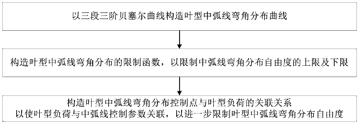
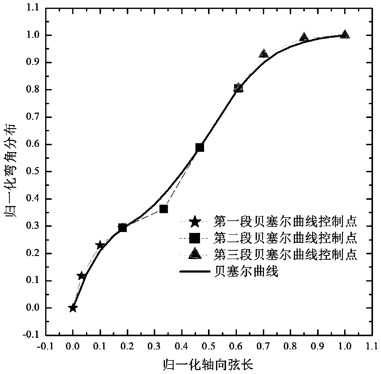
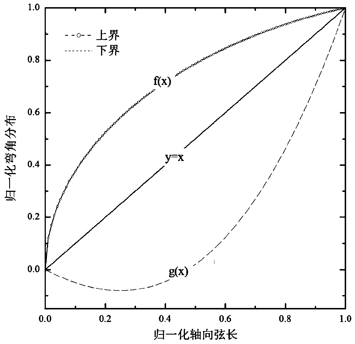
The invention belongs to the technical field of high-load fan and compressor blade profile design, and particularly relates to a blade profile mean camber line design method. The method comprises thefollowing steps: constructing a blade profile mean camber line corner distribution curve by using three sections of three-order Bezier curves; constructing a limiting function of the blade profile mean camber line corner distribution to limit the upper limit and the lower limit of the mean camber line corner distribution freedom degree; and the incidence relation between the blade profile mean camber line corner distribution control points and the blade profile load is constructed, so that the blade profile load is associated with the mean camber line control parameters, and the degree of freedom of blade profile mean camber line corner distribution is further limited. In addition, the invention relates to a blade profile design method which comprises the following steps: obtaining a bladeprofile mean camber line based on the blade profile mean camber line design method; and the obtained blade profile mean camber lines are subjected to superposition thickness distribution to obtain the blade profile.

Description

technical field [0001] The application belongs to the technical field of blade profile design of a high-load fan and a compressor thereof, and in particular relates to a blade profile and a method for designing a mid-arc. Background technique [0002] With the development of small bypass ratio turbofan engines, the load levels of fans and compressors are gradually increasing, and high-load airfoils need to be designed to meet the demand. High-load airfoils usually have large bending angles, high diffusion factors, and high inlet Mach. number, with high design difficulty. [0003] At present, the high-load airfoil mostly adopts multi-arc airfoil, free curve airfoil without definite curve form and constraint conditions. Type design, the airfoil type obtained by this design has the following defects: [0004] 1) The loss is large, so that the efficiency of the compression parts is low under high-speed working conditions; [0005] 2) The range of available angle of attack is ...

Claims


Application Information

Patent Timeline
IPC IPC(8): G06F30/17F04D29/26G06F119/14
CPCF04D29/26Y02T90/00
Inventor 赵清伟刘杰潘若痴
Owner AECC SHENYANG ENGINE RES INST
Learn More