
Flexible vibration damping connection structure

A vibration connection and flexible technology, which is applied in the field of flexible vibration damping connection design of structures, can solve problems such as occupying a large space

Pending Publication Date: 2020-08-14
邱伊萍
View PDF0 Cites 4 Cited by
  • Summary
  • Abstract
  • Description
  • Claims
  • Application Information

AI Technical Summary

Problems solved by technology

[0002] The connection between parts is often involved in the project. At present, the connection parts of some connected parts need to be able to expand and contract, and have a certain degree of flexibility, so as to meet the needs of the connected parts close to or far away from each other, and at the same time have a certain buffer function to meet the requirements of vibration reduction between the connected parts. For this reason, a connecting piece made of elastic material is currently designed to connect the connected parts. Because of its large elastic deformation capacity, it has great Good stretchability can well meet the needs of the connected parts to be close to or far away from each other, and can meet the requirements of vibration damping between the connected parts, but the connecting parts made of elastic materials need to rely on the occurrence of large The elastic deformation method can provide sufficient deformation capacity. In practical application, in order to enable it to have a large amount of elastic deformation, it is often designed to have a large size structure and take up a large space

Method used


Image

  • Flexible vibration damping connection structure
  • Flexible vibration damping connection structure
  • Flexible vibration damping connection structure

Examples


Embodiment Construction

[0033] In order to make the technical solution of the present application and its advantages clearer, the technical solution of the present application will be further clearly and completely described in detail below in conjunction with the accompanying drawings. It can be understood that the specific embodiments described here are only part of the application Examples are only used to explain the present application, not to limit the present application. It should be noted that, for the convenience of description, only the parts related to the present application are shown in the drawings, and other relevant parts can refer to the general design. In the case of no conflict, the embodiments in the application and the technologies in the embodiments Features can be combined with each other to obtain new embodiments.

[0034] In addition, unless otherwise defined, the technical terms or scientific terms used in the description of the application shall have the usual meanings und...


PUM


Abstract

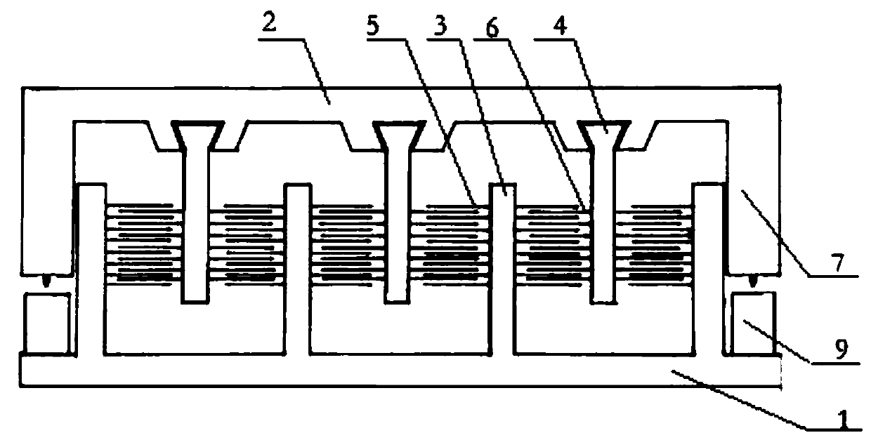
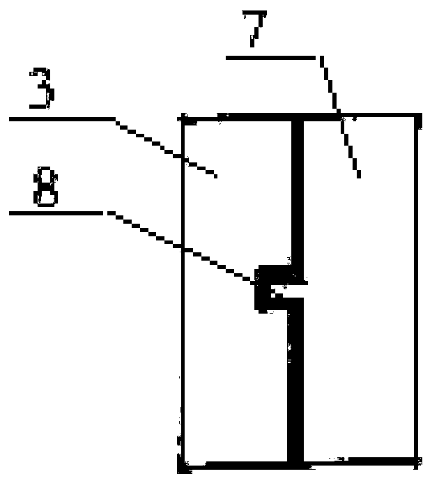
The invention belongs to the technical field of flexible vibration damping connection design of a structure, and particularly relates to a flexible vibration damping connection structure. The flexiblevibration damping connection structure comprises a first supporting plate, a second supporting plate, multiple first supporting strips, multiple second supporting strips, multiple groups of first elastic pieces and multiple groups of second elastic pieces, wherein the second supporting plate is opposite to the first supporting plate; the multiple first supporting strips are arranged between the first supporting plate and the second supporting plate, and one end of each first supporting strip is connected with the first supporting plate; the multiple second supporting strips are arranged between the first supporting plate and the second supporting plate, one end of each second supporting strip is connected with the second supporting plate, and the second supporting strips and the first supporting strips are in cross distribution; each first elastic piece in each group of first elastic pieces is correspondingly arranged on the corresponding first supporting strip in the axial direction;each second elastic piece in each group of second elastic pieces is correspondingly arranged on the corresponding second supporting strip in the axial direction; and the elastic pieces on each firstsupporting strip are in cross distribution with the elastic pieces on the second supporting strip adjacent to the first supporting strip.

Description

[0001] The application belongs to the technical field of structural flexible vibration-damping connection design, and in particular relates to a flexible vibration-damping connection structure. Background technique [0002] The connection between parts is often involved in the project. At present, the connection parts of some connected parts need to be able to expand and contract, and have a certain degree of flexibility, so as to meet the needs of the connected parts close to or far away from each other, and at the same time have a certain buffer function to meet the requirements of vibration reduction between the connected parts. For this reason, a connecting piece made of elastic material is currently designed to connect the connected parts. Because of its large elastic deformation capacity, it has great Good stretchability can well meet the needs of the connected parts to be close to or far away from each other, and can meet the requirements of vibration damping between the...

Claims


Application Information

Patent Timeline
IPC IPC(8): F16F15/06F16F15/02
CPCF16F15/02F16F15/06
Inventor 邱伊萍
Owner 邱伊萍
Learn More