
Stator structure, rotor stator assembly structure with same and assembly method thereof

An assembly structure and stator-rotating technology, which is applied to parts, stators, and non-variable pumps of elastic fluid pumping devices, and can solve the problems of long assembly cycle, cumbersome process, and low assembly efficiency

Active Publication Date: 2020-09-15
AECC SHENYANG ENGINE RES INST
View PDF10 Cites 3 Cited by
  • Summary
  • Abstract
  • Description
  • Claims
  • Application Information

AI Technical Summary

Problems solved by technology

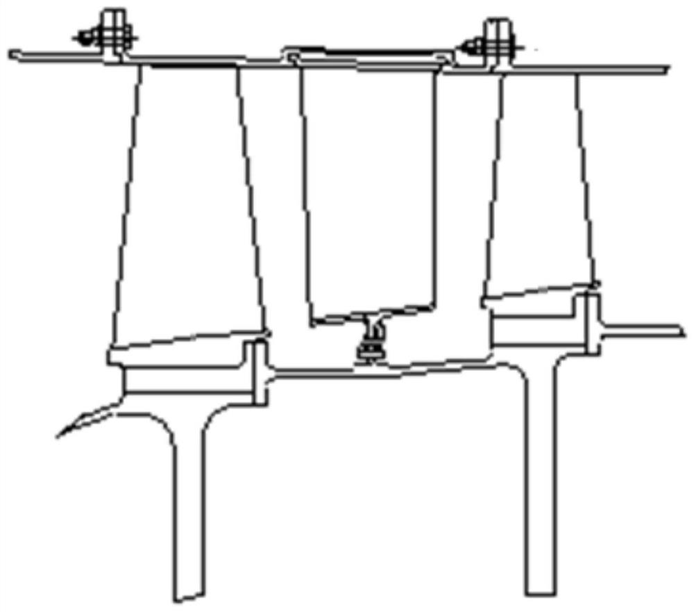
[0003] At present, in order to realize the assembly, the stator structure is usually designed as a split structure, that is, the stator case is designed to be formed by the butt joint of two semi-annular stator cases, and a limit groove is opened in the inner wall of each semi-annular stator case along the circumferential direction. The blade tips of each stator blade are provided with edge plates, and each stator blade is divided into two groups, and each group of stator blades corresponds to a semi-circular stator casing. When assembling the stator structure and rotor components, firstly, each group of stator blades The edge plate at the tip slides into the limit groove of the corresponding half-ring stator casing in turn, rotates to the predetermined position for positioning, and then puts each stator blade between the front-stage rotor blade and the rear-stage rotor blade. The blade root of each stator blade is connected with the outer wall of the stator inner ring sleeved on the rotor drum, and the two semi-circular stator casings are butted to form a stator casing, and the front end of the stator casing is connected to the rear of the front stage installation casing. End docking, rear end docking with the front end of the post-installation casing, the process is cumbersome, the design involves the connection between multiple components, the assembly efficiency is low, and the assembly cycle is long

Method used


Image

  • Stator structure, rotor stator assembly structure with same and assembly method thereof
  • Stator structure, rotor stator assembly structure with same and assembly method thereof
  • Stator structure, rotor stator assembly structure with same and assembly method thereof

Examples


Embodiment Construction

[0039] In order to make the technical solution of the present application and its advantages clearer, the technical solution of the present application will be further clearly and completely described in detail below in conjunction with the accompanying drawings. It can be understood that the specific embodiments described here are only part of the application Examples are only used to explain the present application, not to limit the present application. It should be noted that, for the convenience of description, only the parts related to the present application are shown in the drawings, and other relevant parts can refer to the general design. In the case of no conflict, the embodiments in the application and the technologies in the embodiments Features can be combined with each other to obtain new embodiments.

[0040] In addition, unless otherwise defined, the technical terms or scientific terms used in the description of the application shall have the usual meanings und...


PUM


Abstract

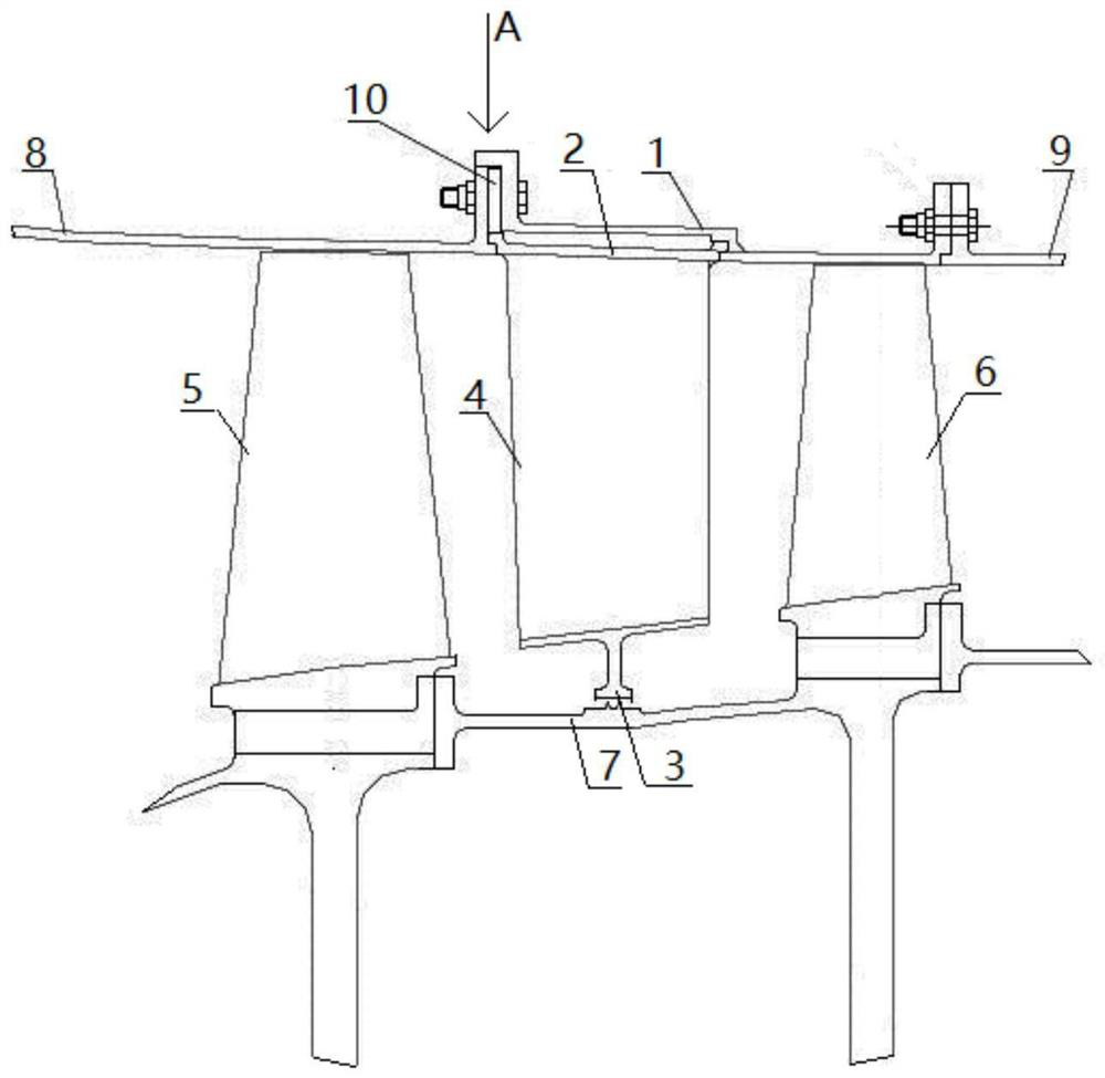
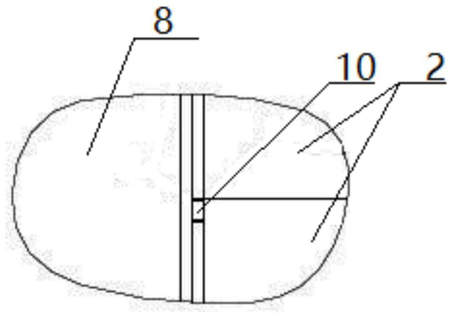
The invention belongs to the technical field of compressor assembly design, and particularly relates to a stator structure. The stator structure comprises a stator casing, two semi-annular edge rings,two semi-annular stator inner rings and two sets of stator blades. The inner wall of the stator casing is provided with an annular limit groove. The two semi-annular edge rings are arranged inside the stator casing and are butt each other to form an edge ring. One end of the edge ring is clamped into the annular limit groove. The two semi-annular stator inner rings are butt each other to form a stator inner ring. Each semi-annular stator inner ring is correspondingly arranged inside a semi-annular edge ring. Each set of the stator blades are arranged in a circumferential direction between thesemi-annular edge ring and the semi-annular stator inner ring corresponding to the semi-annular edge ring. The tip of each stator blade is formed on the inner wall of the corresponding semi-annular edge ring. A blade root is formed on the outer wall of the corresponding semi-annular stator inner ring. In addition, the invention also relates to a rotor stator assembly structure with the stator structure and an assembly method of a rotor stator structure.

Description

technical field [0001] The application belongs to the technical field of compressor assembly design, and in particular relates to a stator structure, a rotor-stator assembly structure and an assembly method thereof. Background technique [0002] The stator structure in the engine compressor includes a stator casing, a stator inner ring located in the stator casing, a plurality of stator blades arranged axially between the stator casing and the stator inner ring, and the tip of each stator blade is connected to the stator The inner wall of the casing is connected, the blade root is connected with the outer wall of the inner ring of the stator, and the assembly structure with the rotor in the engine is that the inner ring of the stator is sleeved on the rotor drum, and the front end of the stator casing is connected to the rear end of the front stage installation casing. Docking, the rear end is docked with the front end of the rear-stage installation casing, and each stator b...

Claims


Application Information

Patent Timeline
IPC IPC(8): F04D29/54F01D9/04F04D29/64
CPCF04D29/542F04D29/544F01D9/042F04D29/644
Inventor 王雅谋王小颖胡丹
Owner AECC SHENYANG ENGINE RES INST
Learn More