
A three-phase transformer with extractable pressing plate

A three-phase transformer, pull-out technology, applied in the field of three-phase transformers, can solve the problems of labor-consuming, cumbersome operation process, danger, etc., and achieve the effect of labor-saving and simple replacement

Active Publication Date: 2021-05-11
精泰电气集团有限公司
View PDF2 Cites 0 Cited by
  • Summary
  • Abstract
  • Description
  • Claims
  • Application Information

AI Technical Summary

Problems solved by technology

[0003] The pressure plate at the bottom of the current three-phase transformer is difficult to take out. If you want to take it out, you need to disassemble the whole body. The operation process is relatively cumbersome. Secondly, the current three-phase transformer cannot clean the dust inside itself, requiring staff Manual cleaning is dangerous on the one hand and labor-intensive on the other hand

Method used


Image

  • A three-phase transformer with extractable pressing plate
  • A three-phase transformer with extractable pressing plate
  • A three-phase transformer with extractable pressing plate

Examples


Embodiment 1

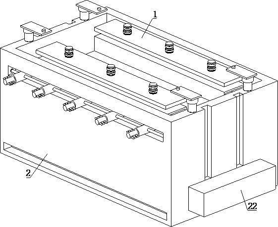
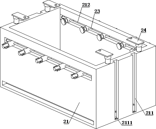
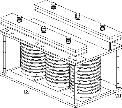
[0031] refer to figure 1 ,3 , 4 and 5, a three-phase transformer with extractable pressure plate, including a main body 1 and an outsourcing mechanism 2, the main body 1 is arranged inside the outsourcing mechanism 2, the main body 1 includes a frame mechanism 11 and a power mechanism 12, the power mechanism 12 Set inside the frame mechanism 11, the power mechanism 12 includes an electric coil winding 121, a bottom plate 122 and an end plate 123, one end of the electric coil winding 121 is provided with a bottom plate 122, and the other end of the electric coil winding 121 is provided with an end plate 123, and the electric coil The winding 121 is connected to the frame mechanism 11 through the bottom plate 122 and the end plate 123. The frame mechanism 11 includes a main lifting rod 111, a pressing plate A112 and a pressing plate B113. One end of the main lifting rod 111 is provided with a pressing plate A112, and the other end of the main lifting rod 111 is provided with Wit...

Embodiment 2

[0036] refer to figure 1 , 3 , 4 and 5, a three-phase transformer with extractable pressure plate, including a main body 1 and an outsourcing mechanism 2, the main body 1 is arranged inside the outsourcing mechanism 2, the main body 1 includes a frame mechanism 11 and a power mechanism 12, the power mechanism 12 Set inside the frame mechanism 11, the power mechanism 12 includes an electric coil winding 121, a bottom plate 122 and an end plate 123, one end of the electric coil winding 121 is provided with a bottom plate 122, and the other end of the electric coil winding 121 is provided with an end plate 123, and the electric coil The winding 121 is connected to the frame mechanism 11 through the bottom plate 122 and the end plate 123. The frame mechanism 11 includes a main lifting rod 111, a pressing plate A112 and a pressing plate B113. One end of the main lifting rod 111 is provided with a pressing plate A112, and the other end of the main lifting rod 111 is provided with W...


PUM


Abstract

The invention discloses a three-phase transformer with extractable pressure plate, which includes a main body mechanism and an outsourcing mechanism, the main body mechanism is arranged inside the outsourcing mechanism, one end of a main lifting rod is provided with a pressure plate A, and the other end of the main lifting rod is provided with a pressure plate B , and the upper surface of the pressure plate A is provided with a sinking groove, both ends of the main lifting rod are fixedly installed with electromagnetic blocks, the main lifting rod is magnetically connected with the pressure plate A and pressure plate B through the electromagnetic block, and the outer surface of the box is provided with a bottom In addition, one end of the support rod is provided with a mounting plate, and the other end of the support rod is connected to the upper surface of the box body. When it is necessary to take out the pressure plate A, use the lifting effect of the main lifting rod to move the power mechanism and the pressure plate B upward as a whole. , and then use the suction cup to absorb the pressure plate B, and at the same time turn off the power supply of the electromagnetic block near the end of the pressure plate A, so that the pressure plate A falls, and finally use the electric push rod to push the pressure plate A out of the bottom groove to achieve the purpose of replacement and the replacement method is relatively simple. Save labor.

Description

technical field [0001] The invention relates to the technical field of three-phase transformers, in particular to a three-phase transformer with a drawable pressure plate. Background technique [0002] In order to input different voltages, the input winding can also use multiple windings to adapt to different input voltages. At the same time, in order to output different voltages, multiple windings can also be used, three independent windings, through different connections (such as: star , triangle), so that it can input three-phase AC power supply, and its output is also the same. This is a three-phase transformer. Three-phase transformers are widely used in circuits with AC 50Hz to 60Hz and voltage below 660V, and are widely used in imported important equipment and precision machine tools. , mechanical and electronic equipment, medical equipment, rectifiers, lighting, etc., various input and output voltage levels of products, connection groups, number and position of adjus...

Claims


Application Information

Patent Timeline
Patent Type & Authority Patents(China)
IPC IPC(8): H01F30/12H01F27/02H01F27/06B08B1/00B08B1/04
CPCH01F30/12H01F27/02H01F27/06B08B1/143B08B1/32
Inventor 姜晏斌林彬财
Owner 精泰电气集团有限公司
Learn More