Steel slag cooling flue gas treatment machine

A technology for flue gas treatment and steel slag, applied in chemical instruments and methods, separation of dispersed particles, filtration of dispersed particles, etc., can solve problems such as blockage of filter holes, environmental pollution, and unguaranteed service life of the flue gas filter mechanism, and achieve Reduce loss, reduce work intensity, and avoid the effect of shortening the service life of the machine

Inactive Publication Date: 2021-02-19
高勇勇
View PDF3 Cites 0 Cited by
  • Summary
  • Abstract
  • Description
  • Claims
  • Application Information

AI Technical Summary

Problems solved by technology

[0002] The current environmental protection treatment method for liquid steel slag in steelmaking plants in the market has the following problems in the operation process: because the traditional environmental protection treatment method for liquid steel slag in steelmaking plants needs to cool down the steel slag before crushing the steel slag, so that the steel slag hardens, and the steel slag is hardened. During the process, a large amount of flue gas will be generated, and some treatment methods do not effectively control the flue gas, and the flue gas is directly discharged into the atmosphere, causing environmental pollution. At the same time, some flue gas filtering mechanisms are likely to cause The filter holes are blocked in a large area, so that the service life of the flue gas filter mechanism cannot be guaranteed, so it is urgent to design a flue gas treatment machine that prevents the filter mechanism from clogging

Method used


Image

  • Steel slag cooling flue gas treatment machine
  • Steel slag cooling flue gas treatment machine
  • Steel slag cooling flue gas treatment machine

Examples


Embodiment Construction

[0019] The following will be combined with Figure 1 to Figure 6 The present invention is described in detail, and the technical solutions in the embodiments of the present invention are clearly and completely described. Apparently, the described embodiments are only part of the embodiments of the present invention, not all of them. Based on the embodiments of the present invention, all other embodiments obtained by persons of ordinary skill in the art without making creative efforts belong to the protection scope of the present invention.

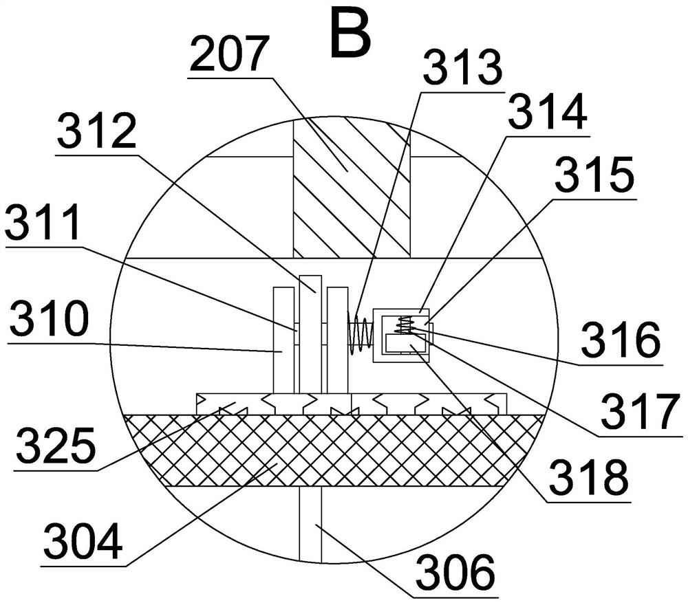
[0020] Such as figure 1 As shown, a steel slag cooling flue gas treatment machine includes a machine body 101, a flue gas discharge channel 102 with an upper side opening is arranged in the body 101, and a funnel-shaped drop is arranged on the lower side wall of the flue gas discharge channel 102. Drop space 103, the small opening on the lower side of the drop space 103 is communicated with a passage space 104 with an opening downward, an...


PUM


Abstract

The invention discloses a steel slag cooling flue gas treatment machine which comprises a machine body, a flue gas exhaust channel with an opening in the upper side is formed in the machine body, a funnel-shaped falling space is formed in the lower side wall of the flue gas exhaust channel in a communicating mode, and a passing space with a downward opening is formed in a small opening in the lower side of the falling space in a communicating mode; an air inlet pipeline is arranged on the right side wall of the passing space in a communicating mode, the air inlet pipeline extends rightwards toenter the external space, the air inlet pipeline is connected with the flue gas input end, filtering of the steel slag cooling flue gas is achieved, and when residues in the flue gas block the filterscreen, the filter screen can be cleaned; the situation that the service life of the machine is shortened due to blockage of the filter screen is avoided, the working intensity of manual maintenanceof the machine is reduced due to the self-cleaning effect of the device, the loss of human resources is reduced, and the maintenance work operation is simple.

Description

technical field [0001] The invention belongs to the field of steelmaking, in particular to a steel slag cooling flue gas processing machine. Background technique [0002] The current environmental protection treatment method for liquid steel slag in steelmaking plants in the market has the following problems in the operation process: because the traditional environmental protection treatment method for liquid steel slag in steelmaking plants needs to cool down the steel slag before crushing the steel slag, so that the steel slag hardens, and the steel slag is hardened. During the process, a large amount of flue gas will be generated, and some treatment methods do not effectively control the flue gas, and the flue gas is directly discharged into the atmosphere, causing environmental pollution. At the same time, some flue gas filtering mechanisms are likely to cause A large area of ​​filter holes is blocked, so that the service life of the flue gas filter mechanism cannot be g...

Claims


Application Information

Patent Timeline
Patent Type & Authority Applications(China)
IPC IPC(8): B01D46/42B01D46/10
CPCB01D46/10B01D46/681
Inventor 高勇勇
Owner 高勇勇
Why Eureka
Try Eureka