
Skimming mud scraper

A kind of scraper and scraper technology, which is applied to sedimentation tanks, feeding/discharging devices of sedimentation tanks, chemical instruments and methods, etc., which can solve the problems of unclean scraping and insufficient scraping.

Inactive Publication Date: 2021-02-19
江苏诺德环保工程有限公司
View PDF3 Cites 0 Cited by
  • Summary
  • Abstract
  • Description
  • Claims
  • Application Information

AI Technical Summary

Problems solved by technology

[0006] However, in the scraping process of the mud scraping equipment disclosed in the prior art, the scraping material is not clean and the scraping material is not su

Method used


Image

  • Skimming mud scraper
  • Skimming mud scraper
  • Skimming mud scraper

Examples


Embodiment 1

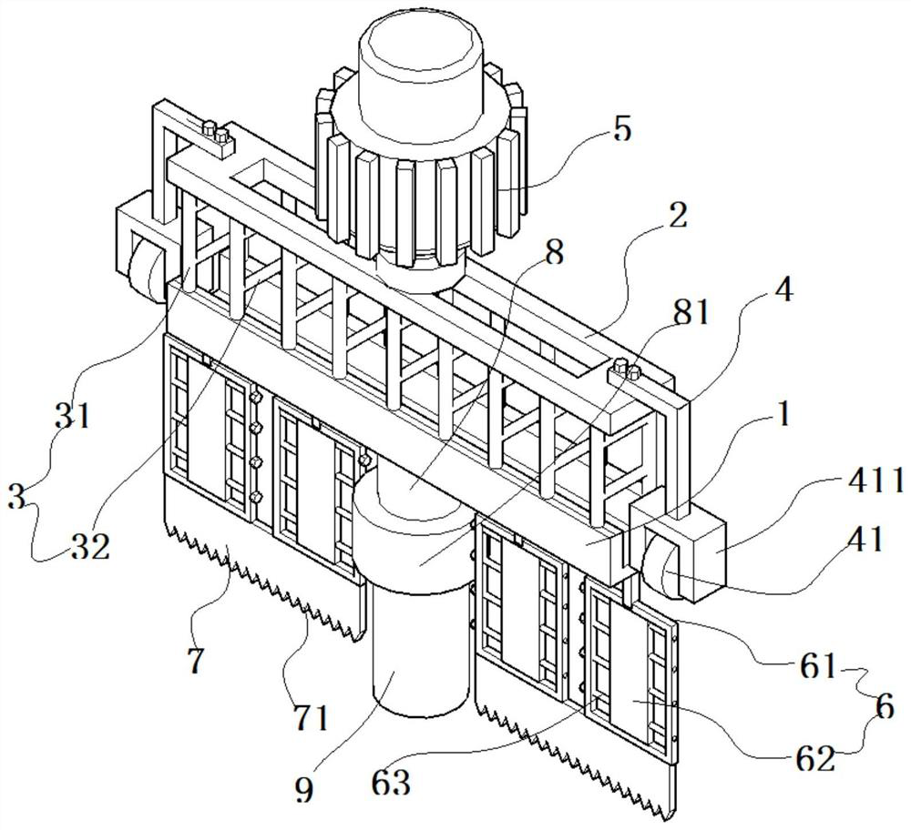
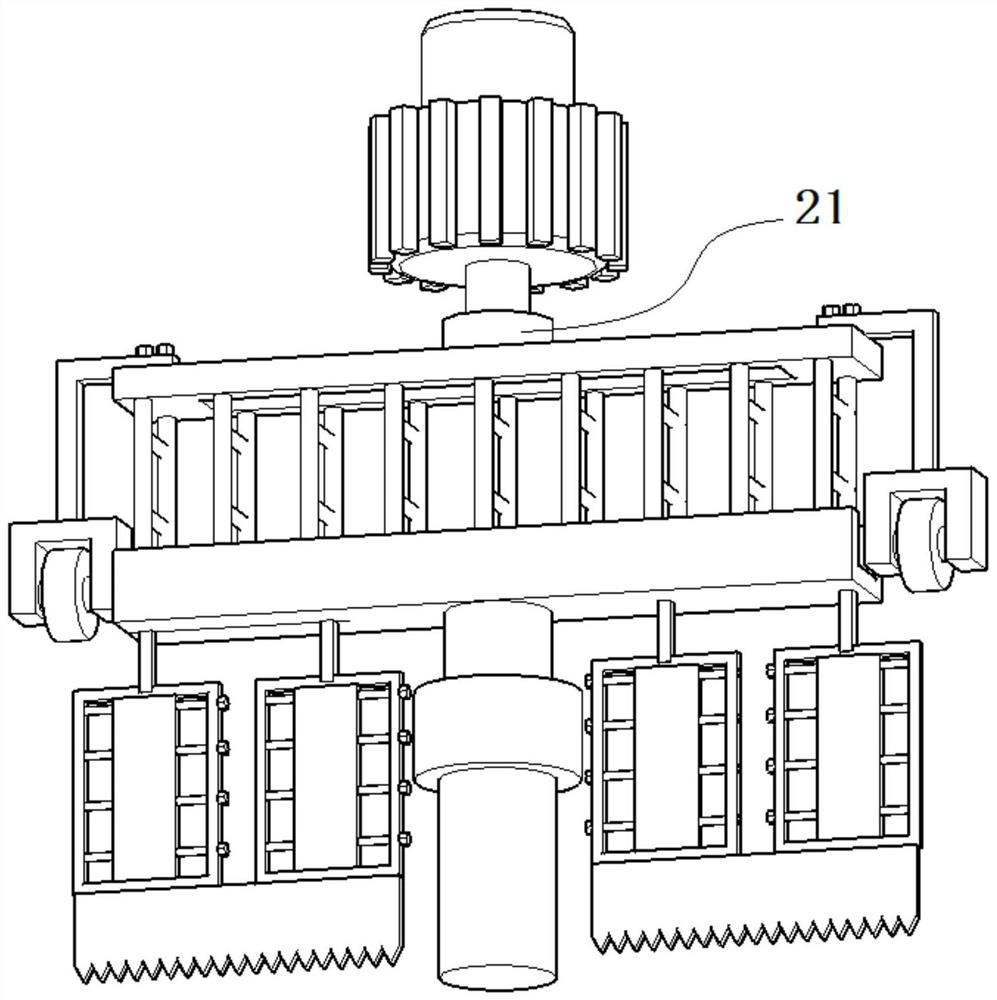
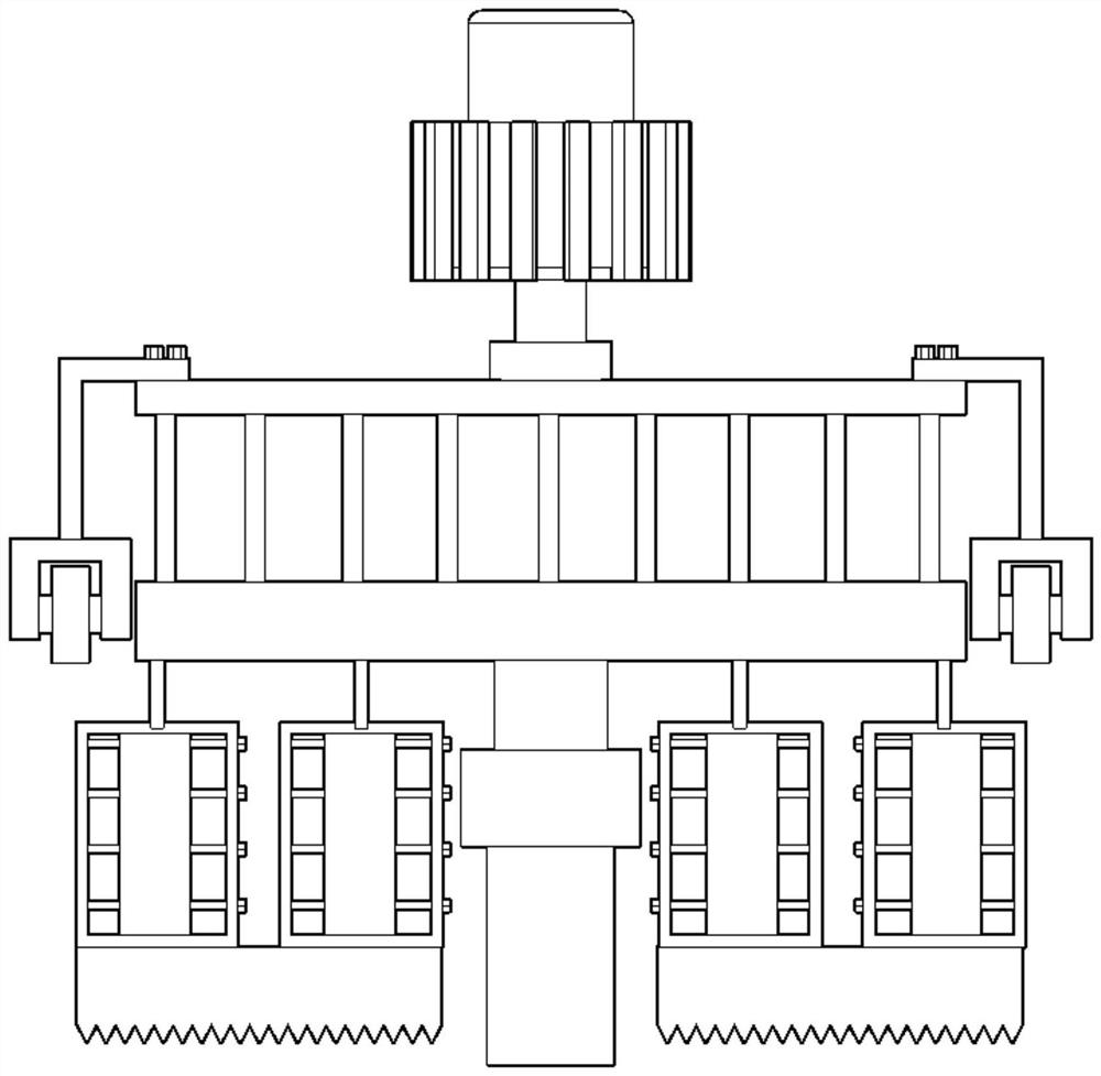
[0039] Such as Figure 1-8 As shown, a skimming mud scraper includes a pillar 9, the top of the pillar 9 is fixedly connected with a turntable seat 81, and the top of the turntable seat 81 is rotatably connected with a rotating column 8, and the top of the rotating column 8 is fixed Connected with a horizontal beam 1.

[0040] The bottom of the above-mentioned horizontal beam 1 is fixedly connected with several mud scraping parts 6 , and the several mud scraping parts 6 are symmetrically distributed on both sides of the pillar 9 . The sludge at the bottom of the sewage tank is scraped off by the scraper 6 .

[0041] The concrete structure of above-mentioned mud scraping part 6 is as follows:

[0042] The mud scraping parts 6 all include a rectangular frame rod 61, and a rectangular opening is opened on the rectangular frame rod 61, and a scraper 62 is arranged in the rectangular opening, and several positioning screws arranged at intervals up and down are threaded on the rec...

Embodiment 2

[0049] Such as Figure 1-8 As shown, a skimming mud scraper includes a pillar 9, the top of the pillar 9 is fixedly connected with a turntable seat 81, and the top of the turntable seat 81 is rotatably connected with a rotating column 8, and the top of the rotating column 8 is fixed Connected with a horizontal beam 1.

[0050] The bottom of the above-mentioned horizontal beam 1 is fixedly connected with several mud scraping parts 6 , and the several mud scraping parts 6 are symmetrically distributed on both sides of the pillar 9 . The sludge at the bottom of the sewage tank is scraped off by the scraper 6 .

[0051] The concrete structure of above-mentioned mud scraping part 6 is as follows:

[0052]The mud scraping parts 6 all include a rectangular frame rod 61, and a rectangular opening is opened on the rectangular frame rod 61, and a scraper 62 is arranged in the rectangular opening, and several positioning screws arranged at intervals up and down are threaded on the rect...


PUM


Abstract

The invention discloses a skimming mud scraper, which comprises a supporting column, a rotary disc base is fixedly connected to the top of the supporting column, a rotary column is rotatably connectedto the top of the rotary disc base, and a horizontal beam column is fixedly connected to the top of the rotary column; the bottom of the horizontal beam column is fixedly connected with a plurality of mud scraping pieces, each mud scraping piece comprises a rectangular frame rod, a rectangular opening is formed in each rectangular frame rod, a scraping plate is arranged in each rectangular opening, the rectangular frame rods are in threaded connection with a plurality of positioning screws which are arranged up and down at intervals, the positioning screws are connected with the scraping plates, and a plurality of scraping teeth are arranged at the bottoms of the scraping toothed plates; the top of the horizontal beam column is fixedly connected with a plurality of suspension rods arranged left and right at intervals, the tops of the suspension rods are fixedly connected with a top end plate, and a driving motor is assembled at the top of the top end plate. By means of the design of the components of the device, sludge materials in the sewage pool can be scraped off, stable movement is achieved through the design of the components of the device, the sludge scraping efficiency is high, and caked materials in the sewage pool can be fully scraped off.

Description

technical field [0001] The invention relates to the technical field of mud scrapers, in particular to a skimming mud scraper. Background technique [0002] In the sewage treatment process, it is often necessary to pump the sewage into the sewage tank for storage. During the sewage storage process, the substances in the sewage, such as sludge, tend to settle on the bottom of the sewage tank. [0003] After the subsequent sewage treatment, such as through flocculant settling treatment, a large amount of sewage still settles in the sewage tank. [0004] The treated sewage is discharged from the sewage tank, and a large amount of sludge that needs to be treated is accumulated in the sewage tank from which the sewage is discharged. [0005] In the prior art, in order to fully and quickly clean up the sludge, the method of scraping is often adopted, that is, the scraper is used to scrape the material, and the material is pushed and transported in a centralized manner. [0006] H...

Claims


Application Information

Patent Timeline
IPC IPC(8): B01D21/18B01D21/24B01D21/06
CPCB01D21/14B01D21/18B01D21/183B01D21/245
Inventor 姚能栋孙天明孙峰
Owner 江苏诺德环保工程有限公司
Learn More