
A Side-Polished Optical Fiber-Microstructure Optical Fiber Fluid Sensing System Based on Photonic Band Gap

A technology of micro-structured optical fiber and photonic bandgap, which is applied in cladding optical fiber, optical waveguide, optical, etc., can solve the problems of limited application range, inability to meet replaceable filling liquid, low detection sensitivity, etc., and achieve convenient manufacturing, throwing The effect of flexible and controllable grinding depth and high sensitivity

Active Publication Date: 2022-07-22
CHONGQING UNIV OF POSTS & TELECOMM
View PDF10 Cites 0 Cited by
  • Summary
  • Abstract
  • Description
  • Claims
  • Application Information

AI Technical Summary

Problems solved by technology

But because the channel is far away from the core, the detection sensitivity is not high
In summary, the current optical fiber fluid control technology has achieved certain research results, but the simple processing technology cannot meet the requirements of replaceable filling fluid, which limits the application range of this technology

Method used


Image

  • A Side-Polished Optical Fiber-Microstructure Optical Fiber Fluid Sensing System Based on Photonic Band Gap
  • A Side-Polished Optical Fiber-Microstructure Optical Fiber Fluid Sensing System Based on Photonic Band Gap
  • A Side-Polished Optical Fiber-Microstructure Optical Fiber Fluid Sensing System Based on Photonic Band Gap

Examples


Embodiment Construction

[0022] The technical solutions in the embodiments of the present invention will be clearly and completely described below with reference to the accompanying drawings in the embodiments of the present invention. Obviously, the described embodiments are only a part of the embodiments of the present invention, rather than all the embodiments. Based on the embodiments of the present invention, all other embodiments obtained by those of ordinary skill in the art without creative efforts shall fall within the protection scope of the present invention.

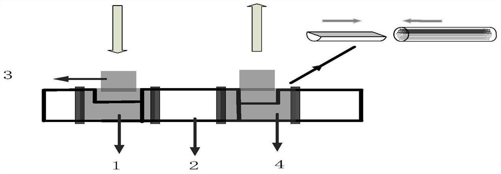
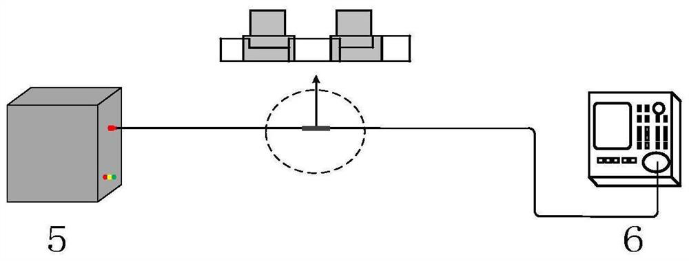
[0023] A side-polished optical fiber-microstructure optical fiber fluid sensing system based on photonic bandgap is a fluid control system, comprising a side-polluted optical fiber, a microstructured optical fiber, a first inflow tee and a second outflow tee. The polishing ports of the two sections of side-polished optical fiber are respectively fused with both ends of the microstructured fiber to form a side-polished optical fiber-mi...


PUM

PropertyMeasurementUnit
refractive indexaaaaaaaaaa

Abstract

The invention belongs to the field of optical fiber fluid control, and in particular relates to a side-throw optical fiber-microstructure optical fiber fluid sensing system based on a photonic band gap, comprising a side-throw optical fiber, a microstructure optical fiber, an inflow tee, an outflow tee, a supercontinuous The light source and the spectrometer, the polishing ports of the two sections of the side-polished optical fiber are respectively fused with the two ends of the microstructured optical fiber to form a double-sided polishing structure of the side-polished optical fiber-microstructured optical fiber-side-polished optical fiber, and the other ends of the two sections of the side-polished optical fiber are respectively The supercontinuum light source and the spectrometer are connected, the polishing areas of the two side-polished optical fibers are embedded in the inflow tee and the outflow tee respectively, and the other ends of the inflow tee and the outflow tee are respectively connected with microstructured fibers The optical fiber fluid sensing system of the present invention can realize real-time detection of flowing liquid, and the depth of the optical fiber polishing area is flexible and controllable. By changing the polishing depth, the number of layers of the microstructure optical fiber fluid channel can be controlled, which affects the sensitivity of the system. It can be widely used in the field of optical sensing.

Description

technical field [0001] The invention belongs to the field of optical fiber fluid control, in particular to a side-throw optical fiber-microstructure optical fiber fluid sensing system based on a photonic band gap. Background technique [0002] Optical fiber microfluidic control technology enables functional materials to flow inside the optical fiber system and fill all the space in the channel through the construction of a fluid circulation device, and interact with the optical field while flowing, which can be widely used in biochemical analysis, environmental monitoring, etc. many fields. [0003] The existing optical fiber fluid sensing systems on the market mainly have the following structures: The SMF-C-PCF-C-SMF structure has high sensitivity, but its small C-shaped fiber brings operational difficulties, and the light leaks seriously and cannot be used. Transport in a liquid core; use of tilted fibers to achieve fluidic control of side-channel photonic crystal fibers....

Claims


Application Information

Patent Timeline
Patent Type & Authority Patents(China)
IPC IPC(8): G01D21/02G02B6/02B01L3/00
CPCG01D21/02G02B6/02347B01L3/502707B01L2200/027
Inventor 郭俊启岳怡婷刘宇杨庆荣崔巍邹新海王昌乐
Owner CHONGQING UNIV OF POSTS & TELECOMM
Learn More