
Fluid-solid coupling inerter

A technology of fluid-solid coupling and inerter, which is applied in the field of vibration control, can solve problems such as inconvenience, insufficient inertia coefficient, and complex structure of mechanical inerter, and achieve the effect of strengthening engineering value, reducing dynamic response, and ensuring structural safety

Inactive Publication Date: 2021-02-12
TONGJI UNIV
View PDF16 Cites 4 Cited by
  • Summary
  • Abstract
  • Description
  • Claims
  • Application Information

AI Technical Summary

Problems solved by technology

However, the mechanical inertia structure is relatively complicated, which is inconvenient in practical application
Different from mechanical inertia, the structure of hydraulic inertia (fluid inertia) which achieves inertia characteristics by changing the flow velocity is relatively simple and easy to realize. The apparent quality and efficiency advantages are not enough to meet the requirements of practical applications

Method used


Image

  • Fluid-solid coupling inerter
  • Fluid-solid coupling inerter
  • Fluid-solid coupling inerter

Examples


Embodiment

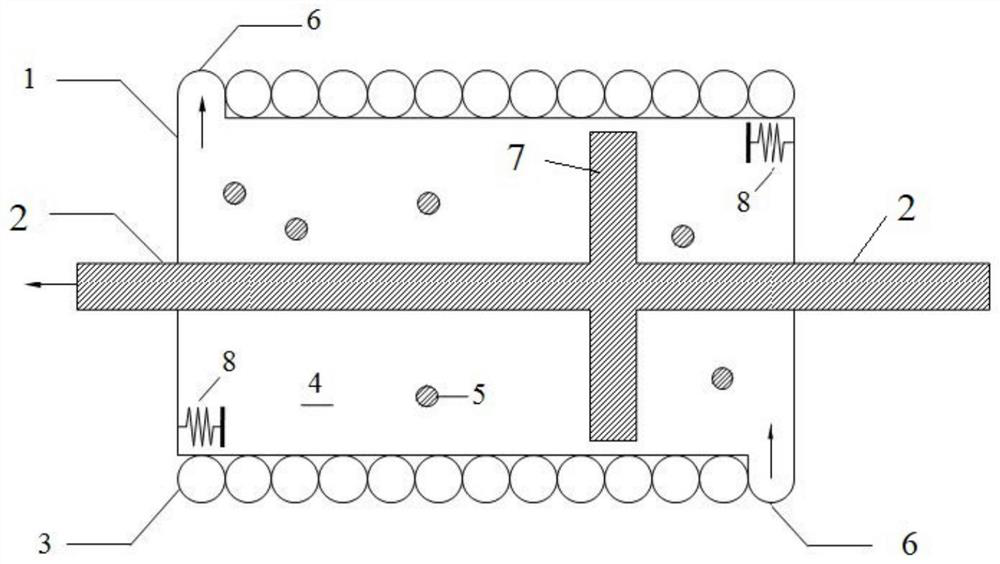
[0037] Such as figure 1 As shown, a fluid-solid coupling inerter, the inerter includes a cylinder 1, a piston 7 that is movably located inside the cylinder 1 in the axial direction and divides the interior of the cylinder 1 into two chambers, and is wound around the The spiral pipe 3 on the outer wall of the cylinder body 1, the two sides of the piston 7 are all vertically provided with a piston rod 2, and the piston rod 2 runs through the cylinder body 1 movably in the axial direction, and the side walls of the two chambers are provided with The pipe port 6 connected to the end of the spiral pipe 3 can be provided with a switch control valve (omitted in the figure), and the inner wall of the chamber is provided with a buffer spring 8. On the side wall in the vertical direction of the body 1, the cylinder body 1 and the spiral pipe 3 are filled with fluid 4 (the arrow in the figure is the direction of fluid flow), and the fluid 4 contains solid particles 5 . Wherein, the mate...


PUM


Abstract

The invention relates to a fluid-solid coupling inerter which comprises a cylinder body (1), a piston (7) and a spiral pipeline (3). The piston (7) is movably located in the cylinder body (1) and divides the interior of the cylinder body (1) into two cavities, the spiral pipeline (3) is wound on the outer side wall of the cylinder body (1) in the circumferential direction, the spiral pipeline (3)is communicated with the cylinder body (1), and the cylinder body (1) and the spiral pipeline (3) are filled with fluid (4). The fluid (4) contains solid particles (5). Compared with the prior art, the inerter is simple in structure, the synergistic effect of the apparent mass (inerter coefficient) of the inerter can be further enhanced, and meanwhile the inerter has the energy consumption synergistic function.

Description

technical field [0001] The invention relates to the technical field of vibration control, in particular to a fluid-solid coupling inerter. Background technique [0002] Inertia is a kind of two-point inertial element, which has potential application in vibration control. Inertia control technology using inertial for vibration control is expected to become a new generation mainstream solution to improve the performance of structures or equipment. Different from the traditional single-end mass element, the output force of the inertial element is related to the relative acceleration of the two ends, and the ratio of the output force to the relative acceleration of the two ends is the apparent mass of the inertial element, also known as the inertial coefficient. The inertia coefficient produced by inertia can be much greater than its own physical mass, which is called the apparent mass synergy characteristic of inertia. The inertia characteristics of the two ends of the inertia...

Claims


Application Information

Patent Timeline
IPC IPC(8): F16F9/20F16F15/22
CPCF16F9/20F16F15/22F16F2222/08F16F2230/06
Inventor 张瑞甫曹嫣如吴敏君
Owner TONGJI UNIV
Learn More