Eureka AIR delivers breakthrough ideas for toughest innovation challenges, trusted by R&D personnel around the world.

Multi-rope lifting system for ultra-deep vertical shaft and guiding method of multi-rope lifting system

A technology for lifting systems and vertical shafts, which is applied to lifting equipment, elevators, transportation and packaging in mines. It can solve the problems of large gear size, large moment of inertia, large load, etc., and achieve reduced axial spacing and uniform traction force distribution. , The effect of prolonging the effective service life

Active Publication Date: 2021-02-12
CHINA UNIV OF MINING & TECH
View PDF12 Cites 4 Cited by
  • Summary
  • Abstract
  • Description
  • Claims
  • Application Information

AI Technical Summary

Problems solved by technology

In this application, the wire rope group of each main shaft device pulls the same lifting container, which causes a large torque difference between the main shaft device pulling the empty container and the heavy-duty container, and the gear transmission system between the two main shaft devices needs to bear Larger loads, and the required gear size is larger, resulting in a larger moment of inertia

Method used


Image

  • Multi-rope lifting system for ultra-deep vertical shaft and guiding method of multi-rope lifting system
  • Multi-rope lifting system for ultra-deep vertical shaft and guiding method of multi-rope lifting system
  • Multi-rope lifting system for ultra-deep vertical shaft and guiding method of multi-rope lifting system

Examples


Embodiment 1

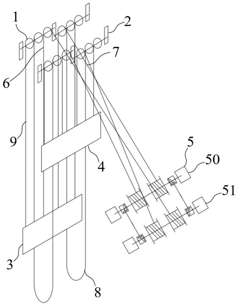
[0086] The ultra-deep vertical shaft multi-rope hoisting system of this embodiment includes,

[0087] The upper guide wheel system 1 is provided with several guide wheels;

[0088] The lower guide wheel system 2 is arranged under the side of the upper guide wheel system 1, and several guide wheels are arranged on the lower guide wheel system 2;

[0089] The front lifting container 3 is located directly below the upper guide wheel train 1;

[0090] The rear lifting container 4 is located directly below the lower guide wheel train 2;

[0091] Drive unit 5, which drives the lifting of the front lifting container 3 and the rear lifting container 4;

[0092] The front lifting rope 6, which has several roots, rides on the upper guide wheel train 1, and one end of the front lifting rope 6 is connected to the top of the front lifting container 3, and the other end is connected to the drive unit 5;

[0093] The rear hoisting rope 7, which has several roots, rides on the lower guide ...

Embodiment 2

[0101] The ultra-deep vertical shaft multi-rope hoisting system of this embodiment is further improved on the basis of Embodiment 1, and the drive unit 5 includes a front drive part 50 and a rear drive part 51 arranged in parallel to each other;

[0102] The front drive unit 50 includes,

[0103] Drive motor-500, which provides driving force;

[0104] Main shaft one 501, which rotates under the drive of drive motor one 500;

[0105] Drum 1 502, which has several, is installed on the main shaft 1 501, and the drum 1 502 is wound with front hoisting rope 6 or rear hoisting rope 7;

[0106] The rear drive unit 51 includes,

[0107] Driving motor 2 510, which provides driving force;

[0108] Main shaft two 511, which rotates under the drive of driving motor two 510;

[0109] Drum 2 512, which has several, is installed on the main shaft 2 511, and the drum 2 512 is wound with front hoisting rope 6 or rear hoisting rope 7;

[0110] The front lifting rope 6 wound on the first dr...

Embodiment 3

[0116] The ultra-deep vertical shaft multi-rope hoisting system of this embodiment is further improved on the basis of Embodiments 1 and 2. At least one front hoisting rope 6 and at least one rear hoisting rope 7 are wound on the front driving part 50, and,

[0117] At least one front lifting rope 6 and at least one rear lifting rope 7 are wound on the rear driving part 51;

[0118] The front hoisting cord 6 and the rear hoisting cord 7 wound around the same drive part are wound in opposite directions.

[0119] The winding mode of the front lifting rope 6 and the rear lifting rope 7 of the present embodiment is as follows: image 3 , Figure 4 and Figure 6 As shown, different hoisting ropes are wound on different drums of the same drive unit.

[0120] Specifically, the front lifting container 3 of the present embodiment is drawn by two front lifting ropes 6, and the rear lifting container 4 is drawn by two rear lifting ropes 7. The upper guide wheel system 1 is provided w...


PUM


Abstract

The invention discloses a multi-rope lifting system for an ultra-deep vertical shaft and a guiding method of the multi-rope lifting system, and belongs to the technical field of mine lifting. The multi-rope lifting system comprises an upper guiding wheel system, a lower guiding wheel system, a front lifting container, a rear lifting container, a driving unit, a front lifting rope, a rear lifting rope, a tail rope and a plurality of balance head ropes, wherein the front lifting rope is lapped on the upper guiding wheel system, one end of the front lifting rope is connected with the top of the front lifting container, and the other end of the front lifting rope is connected with the driving unit; the rear lifting rope is lapped on the lower guiding wheel system, one end of the rear lifting rope is connected with the top of the rear lifting container, and the other end of the rear lifting rope is connected with the driving unit; one end of the tail rope is connected with the bottom of thefront lifting container, and the other end of the tail rope is connected with the bottom of the rear lifting container; and the balance head ropes are lapped on the upper guiding wheel system, one end of each balance head rope is connected with the top of the front lifting container, and the other end of each balance head rope is connected with the top of the rear lifting container. According tothe multi-rope lifting system, the balance head ropes are arranged, so that the traction load borne by the driving unit is greatly reduced, the effective service life of the driving unit is greatly prolonged, and the multi-rope lifting system for the ultra-deep vertical shaft can carry out lifting operation with larger load.

Description

technical field [0001] The invention belongs to the technical field of mine hoisting, and more specifically relates to an ultra-deep shaft multi-rope hoisting system and a guiding method thereof. Background technique [0002] At present, for the hoisting of deep wells exceeding 1800m, the single-rope winding hoisting system is used to be affected by the weight of the wire rope and the size of the hoisting drum, and the payload is small, while the double-rope Blair type hoist overcomes the small payload of the single-rope winding hoist. Disadvantages, but compared to the large load lifting capacity that can be achieved by 4 or 6 steel wire ropes through multi-rope friction, it is particularly insufficient, and the arrangement of the drum will be difficult due to the increase in the number of winding steel wire ropes. [0003] The existing multi-rope friction hoist has a large fluctuating stress on the wire rope due to the self-weight of the wire rope and the load of the conta...

Claims


Application Information

Patent Timeline
Patent Type & Authority Applications(China)
IPC IPC(8): B66B7/10B66B7/02B66B15/02B66B15/08
CPCB66B7/10B66B7/023B66B15/02B66B15/08
Inventor 曹国华张圆哲朱真才刘善增彭玉兴李佩瑶刘志凯罗刚
Owner CHINA UNIV OF MINING & TECH
Why Eureka
Eureka Blog
Learn More