R-shaped buckle forming device for sewage treatment
A technology for sewage treatment and forming equipment, which is applied in the field of R-type buckle forming equipment for sewage treatment. It can solve the problems of low working efficiency of R-type buckles and inconsistent shapes and sizes of R-type buckles, so as to facilitate work and avoid injuries. , the effect of increasing safety
- Summary
- Abstract
- Description
- Claims
- Application Information
AI Technical Summary
Problems solved by technology
Method used
Image
Examples
Embodiment 1
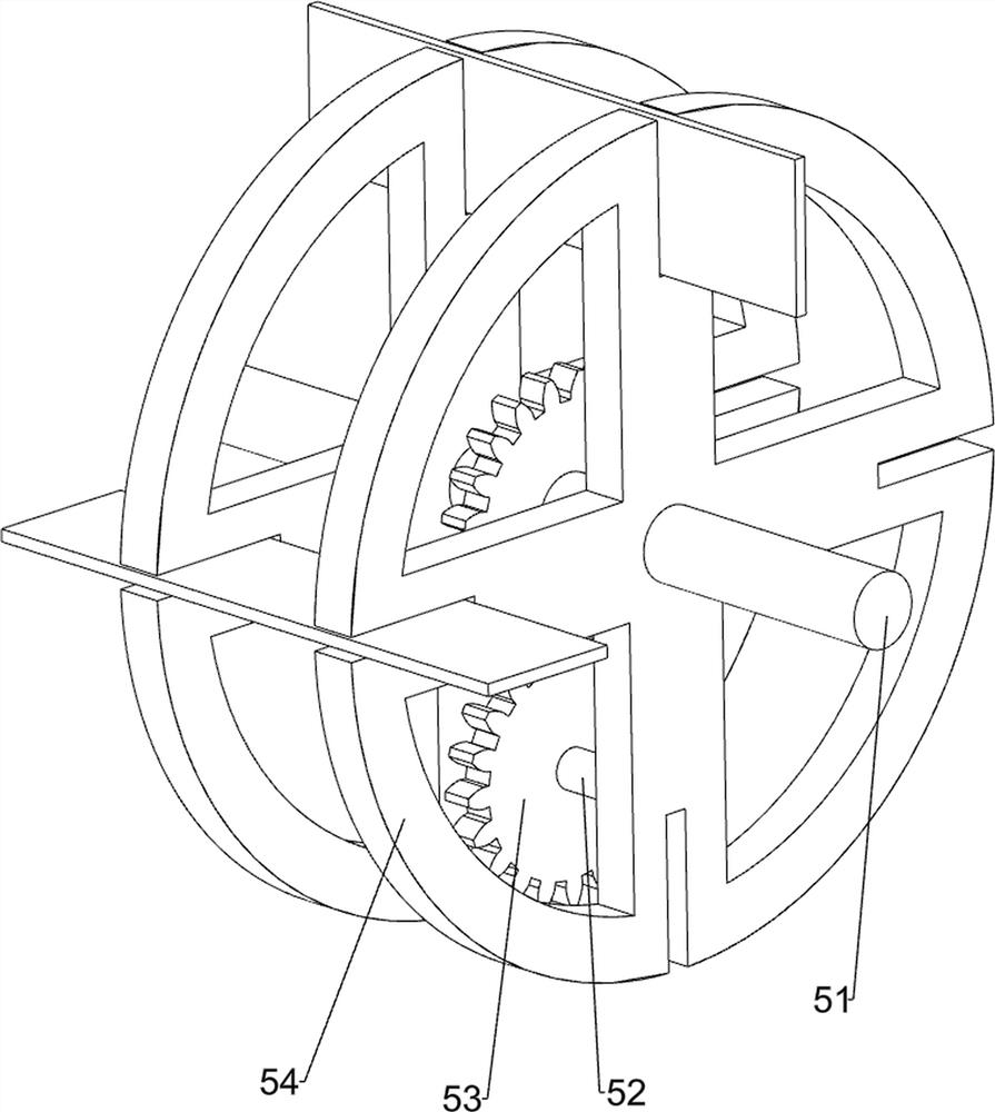
[0057] A kind of R-type buckle forming equipment for sewage treatment, such as figure 1 As shown, it includes a mounting plate 1, a servo motor 2, a material storage box 9, an extruding mechanism 3, a transmission mechanism 4, a first unloading mechanism 5, and an extruding reset mechanism 6. There is a servo motor 2, a material storage box 9 is arranged on the left side of the top front side of the installation plate 1, an extrusion mechanism 3 is arranged between the upper left side of the front side of the installation plate 1 and the output shaft of the servo motor 2, and an extrusion mechanism 3 is arranged on the front side of the right part of the installation plate 1. A transmission mechanism 4 is provided between the lower side and the extruding mechanism 3 , a first unloading mechanism 5 is arranged in the middle part on the right side of the mounting plate 1 , and an extruding reset mechanism 6 is arranged in the upper right side of the storage box 9 .
[0058] When...
Embodiment 2
[0060] On the basis of Example 1, such as figure 2 , image 3 and Figure 4As shown, the extruding mechanism 3 includes a first rotating shaft 31, a rotating disc 32, a first slider 33, a second slider 34, a slide rail 35, a first sliding rod 36 and an extrusion die 37, and the servo motor 2 outputs The shaft is provided with a first rotating shaft 31, the front portion of the first rotating shaft 31 is provided with a rotating disc 32, the outer side of the rotating disc 32 is rotatably provided with a first slider 33, and the bottom of the first slider 33 is slidably provided with a second slider. Block 34, a slide rail 35 is provided on the upper left side of the front side of the mounting plate 1, and the first slide block 33 and the second slide block 34 all slide in the slide rail 35, and a first slide bar 36 is provided in the middle of the bottom of the second slide block 34 , the lower part of the first sliding rod 36 is slidingly connected to the middle of the bot...
Embodiment 3
[0067] On the basis of Example 2, such as Figure 5 , Figure 6 and Figure 7 As shown, the extrusion reset mechanism 6 includes a fifth rotating shaft 61, a rotating block 62 and a first elastic member 63, and the upper part of the right side of the storage box 9 is symmetrically provided with the fifth rotating shaft 61 front and back, and the fifth rotating shaft 61 is of a rotating type. A rotating block 62 is provided, and a first elastic member 63 is arranged in the middle of the upper right side of the material storage box 9 , and the bottom of the rotating block 62 is in contact with the top of the first elastic member 63 .
[0068] When the toggle block 46 moved the iron sheet to the left to the bottom of the extrusion die 37, the extrusion die 37 squeezed the iron sheet downward and squeezed the iron sheet between the rotating blocks 62, and the rotating block 62 rotated the iron The sheet is extruded and formed, and then the extrusion die 37 moves upwards to reset...
PUM
 Abstract
Description
Claims
Application Information
 - R&D Engineer
- R&D Manager
- IP Professional
- Industry Leading Data Capabilities
- Powerful AI technology
- Patent DNA Extraction
Browse by: Latest US Patents, China's latest patents, Technical Efficacy Thesaurus, Application Domain, Technology Topic, Popular Technical Reports.
© 2024 PatSnap. All rights reserved.Legal|Privacy policy|Modern Slavery Act Transparency Statement|Sitemap|About US| Contact US: help@patsnap.com


