
Defect detection method and system for particles in bubble cap plate based on vision

A defect detection and blister board technology, which is applied in the directions of optical testing defects/defects, measuring devices, instruments, etc., can solve the problem of high cost, and achieve the effects of low cost, low extraction difficulty and high detection reliability.

Active Publication Date: 2021-02-09
SHANGHAI DIANJI UNIV
View PDF14 Cites 3 Cited by
  • Summary
  • Abstract
  • Description
  • Claims
  • Application Information

AI Technical Summary

Problems solved by technology

However, this patent needs to rely on specialized imaging equipment, which is costly

Method used


Image

  • Defect detection method and system for particles in bubble cap plate based on vision
  • Defect detection method and system for particles in bubble cap plate based on vision
  • Defect detection method and system for particles in bubble cap plate based on vision

Examples


Embodiment 1

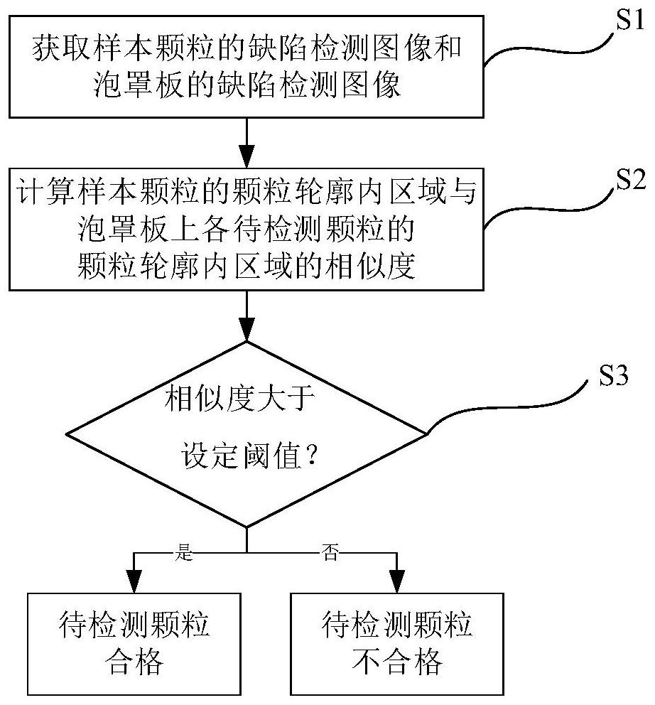
[0036] A vision-based defect detection method for particles in blister sheets, which are in the shape of circular flakes such as figure 1 , the method is specifically:

[0037] S1: Obtain the defect detection image P of the sample particles 1 and the defect detection image of the blister plate P 2 , P 1 Particle profile containing sample particles, P 2 Contains the particle profile of each particle to be detected on the blister plate;

[0038] S2: Through the image similarity function Sim(B 0 , B 1 ) Calculate the similarity of the area in the particle outline of the sample particle and the area in the particle outline of the particle to be detected, B 0 is the apparent information of the area within the particle outline of the sample particle, B 1 is the apparent information of the area within the particle outline of the particle to be detected, Sim(B 0 , B 1) is the product of the color similarity function and the structural similarity function, the structural simil...

Embodiment 2

[0054] In this embodiment, the shape of the particles is capsule-like, the particle profile is a waist-shaped profile, and the size parameters of the particle profile are the diameters and the distance between the centers of the two semicircles of the waist-shaped profile, and the error between the diameter of the two semi-circles and the set diameter is equal It is within the error range of the set diameter, and the error between the distance between the centers of the two semicircles and the set distance is also within the error range of the set distance. Others are the same as in Example 1.

Embodiment 3

[0056] In this embodiment, the image similarity function is a similarity function based on deep learning, and the others are the same as in Embodiment 1.


PUM


Abstract

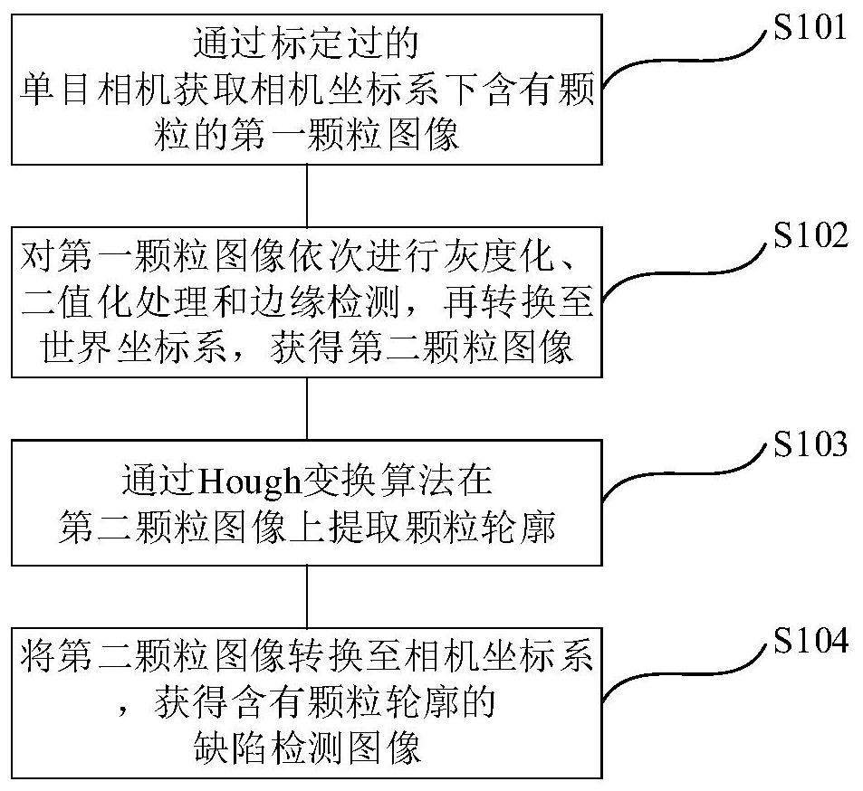
The invention relates to a defect detection method and system for particles in a bubble cap plate based on vision. The method specifically comprises the steps of obtaining a defect detection image P1of sample particles and a defect detection image P2 of the bubble cap plate, wherein defect detection images comprise particle contours; and calculating the similarity of areas in particle contours ofthe sample particles and the to-be-detected particles through an image similarity function, and judging whether the to-be-detected particles are qualified or not according to the similarity. The acquisition process of the defect detection image comprises the steps of shooting a first particle image through a monocular camera, performing graying, binarization processing and edge detection on the image, converting the image to a world coordinate system to obtain a second particle image, extracting particle contours of particles on the image, wherein an error between the size parameter of the particle contour and the set size parameter is within a set error range, and then converting to a camera coordinate system to obtain a defect detection image containing the particle contour. Compared with the prior art, the method has the advantages of low cost, wide application range, high reliability and the like.

Description

technical field [0001] The invention relates to the field of machine vision, in particular to a vision-based defect detection method and system for particles in a blister plate. Background technique [0002] Blister board tablets often require inspectors to inspect the defects of the tablets before leaving the factory. This link adopts a manual method that not only has high work intensity but also slow detection speed. At present, the method of automatic defect detection through vision has emerged as the times require. Under the control of external environmental conditions, the detection technology of tablets or capsules under the same or monotonous background has been relatively mature, but for the identification of tablets loaded into the blister board on the conveyor belt, due to the accuracy of the conveyor belt transmission and the existence of the blister board in the background Instead of being monotonous, using grayscale images and then performing edge detection wil...

Claims


Application Information

Patent Timeline
Patent Type & Authority Applications(China)
IPC IPC(8): G01N21/88
CPCG01N21/8851G01N2021/8887Y02P90/30
Inventor 张晓宇段振峰石金玉王金青王晨曦
Owner SHANGHAI DIANJI UNIV
Learn More