
Torsional vibration damping system for hydrodynamic torque coupling device

A technology of torsional vibration and hydraulic torque, applied in vibration suppression adjustment, spring/shock absorber, mechanical equipment, etc., can solve problems such as large assembly tolerance, system cannot work stably, component manufacturing cost and assembly cost increase, etc. , to reduce design and production costs, facilitate compact setups, and increase the number of parts

Pending Publication Date: 2021-02-09
VALEO KAPEC TORQUE CONVERTERS NANJING CO LTD
View PDF0 Cites 0 Cited by
  • Summary
  • Abstract
  • Description
  • Claims
  • Application Information

AI Technical Summary

Problems solved by technology

In the prior art, in order to meet the different requirements of the torsional vibration damping system, it is often necessary to change the setting of the elastic component, and the change of the setting of the elastic component often leads to the change of other components used to hold the elastic component, namely Requires specific design and manufacture of elastic components and related other components for specific performance requirements, resulting in low product standardization and low cost-effectiveness
In addition, existing torsional vibration damping systems usually only have elastic components that act simultaneously, that is, such elastic components are arranged as a primary damping structure, so that they cannot satisfy both good vibration damping and efficient torque transmission.
Moreover, the existing torsional vibration damping system often involves too many components, and the assembly process is complicated, which introduces a larger assembly tolerance, making the system unable to work stably, and at the same time making the manufacturing cost and assembly cost of the components increases accordingly and is detrimental to achieving a compact overall build

Method used


Image

  • Torsional vibration damping system for hydrodynamic torque coupling device
  • Torsional vibration damping system for hydrodynamic torque coupling device
  • Torsional vibration damping system for hydrodynamic torque coupling device

Examples


Embodiment Construction

[0044] In order to make the purpose, technical solution and advantages of the technical solution of the present invention clearer, the technical solutions of the embodiments of the present invention will be clearly and completely described below in conjunction with the drawings of specific embodiments of the present invention. The same reference numerals in the figures represent the same parts. It should be noted that the described embodiments are some of the embodiments of the present invention, but not all of the embodiments. Based on the described embodiments of the present invention, all other embodiments obtained by persons of ordinary skill in the art without creative efforts shall fall within the protection scope of the present invention.

[0045] Unless otherwise defined, the technical terms or scientific terms used herein shall have the usual meanings understood by those skilled in the art to which the present invention belongs. "First", "second" and similar words us...


PUM


Abstract

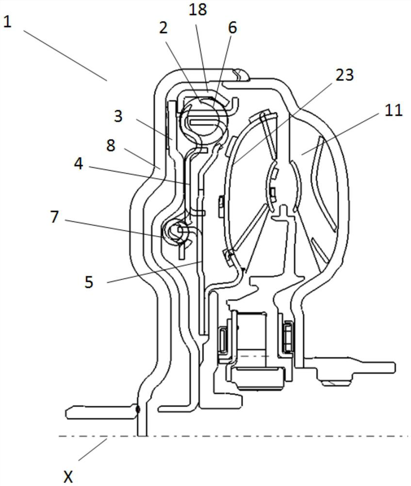
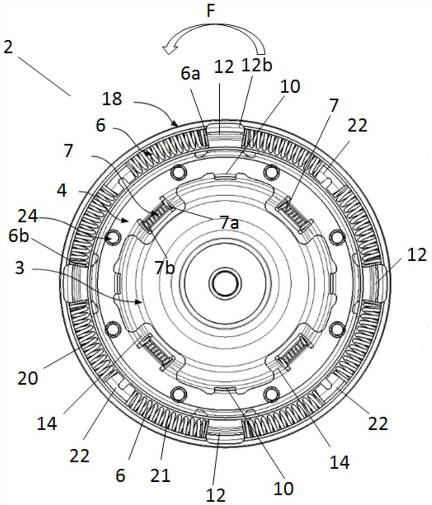
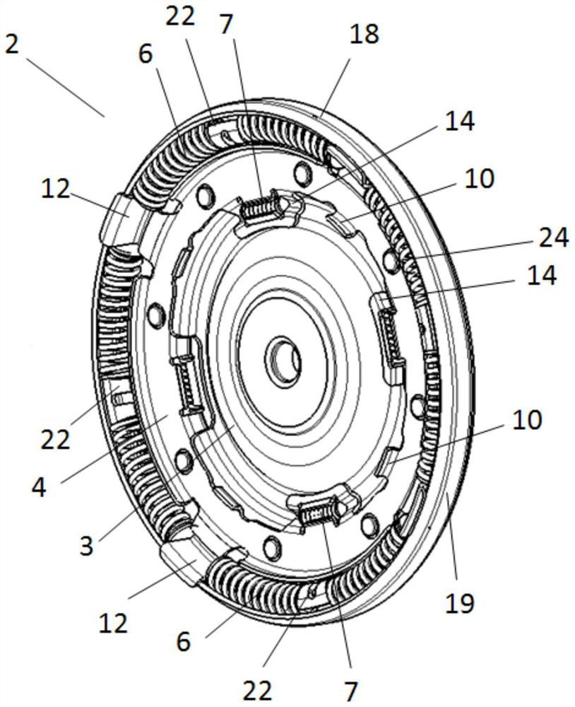
The invention relates to a torsional vibration damping system for a hydrodynamic torque coupling device. The system comprises a piston disc, a retaining disc fixedly connected with the piston disc, adriven disc, a plurality of primary elastic assemblies retained at the radial outer side of the retaining disc, and a plurality of secondary elastic assemblies retained at the radial inner side of theretaining disc. When the piston disc rotates, the primary elastic assemblies can receive torque from the retaining disc and transmit the torque to the driven disc, so that the driven disc can rotateby an angle stroke relative to the retaining disc, in the first section of angle stroke, the primary elastic assemblies are compressed, and the secondary elastic assemblies are not compressed; in thesecond section of angular stroke, the secondary elastic assemblies are compressed between the retaining disc and the driven disc, and the primary elastic assemblies are further compressed; and a stopping window is arranged in the driven disc, a stopping protruding piece is arranged on the retaining disc, and the stopping protruding piece abuts against the edge of the corresponding stopping windowto stop at the end point of the angle stroke. The invention also relates to an associated hydrodynamic torque coupling device and an associated motor vehicle.

Description

technical field [0001] The invention relates to a torsional vibration damping system for a hydrodynamic torque coupling, to a hydrodynamic torque coupling comprising such a torsional vibration damping system, and to a motor vehicle comprising such a hydrodynamic torque coupling. Background technique [0002] The torsional vibration damping system used in the hydraulic torque coupling device in the prior art usually includes an elastic component for transmitting torque and damping vibration, and the setting of the elastic component, such as its size, distribution, hardness, etc. have an important impact. In the prior art, in order to meet the different requirements of the torsional vibration damping system, it is often necessary to change the setting of the elastic component, and the change of the setting of the elastic component often leads to the change of other components used to hold the elastic component, namely The elastic components and their related other components ...

Claims


Application Information

Patent Timeline
Patent Type & Authority Applications(China)
IPC IPC(8): F16F15/123
CPCF16F15/12306F16F15/1232
Inventor 李茂辉胡勋毕荣麟韩冬梅
Owner VALEO KAPEC TORQUE CONVERTERS NANJING CO LTD
Learn More