Steel-concrete composite beam

A technology for steel-concrete composite beams and steel beams, applied in the field of composite beams, can solve problems such as failure of automatic adjustment and balance of concrete slabs, reduced safety performance, and occurrence of safety accidents.

Active Publication Date: 2021-02-09
GUIZHOU ROAD & BRIDGE GRP
View PDF10 Cites 0 Cited by
  • Summary
  • Abstract
  • Description
  • Claims
  • Application Information

AI Technical Summary

Problems solved by technology

[0005] The purpose of the present invention is to provide a steel-concrete composite beam to solve the problem that in the prior art, one side of the concrete slab cannot automatically adjust the balance after being til

Method used


Image

  • Steel-concrete composite beam
  • Steel-concrete composite beam

Examples


Embodiment Construction

[0019] The following will clearly and completely describe the technical solutions in the embodiments of the present invention with reference to the accompanying drawings in the embodiments of the present invention. Obviously, the described embodiments are only some, not all, embodiments of the present invention. Based on the embodiments of the present invention, all other embodiments obtained by persons of ordinary skill in the art without making creative efforts belong to the protection scope of the present invention.

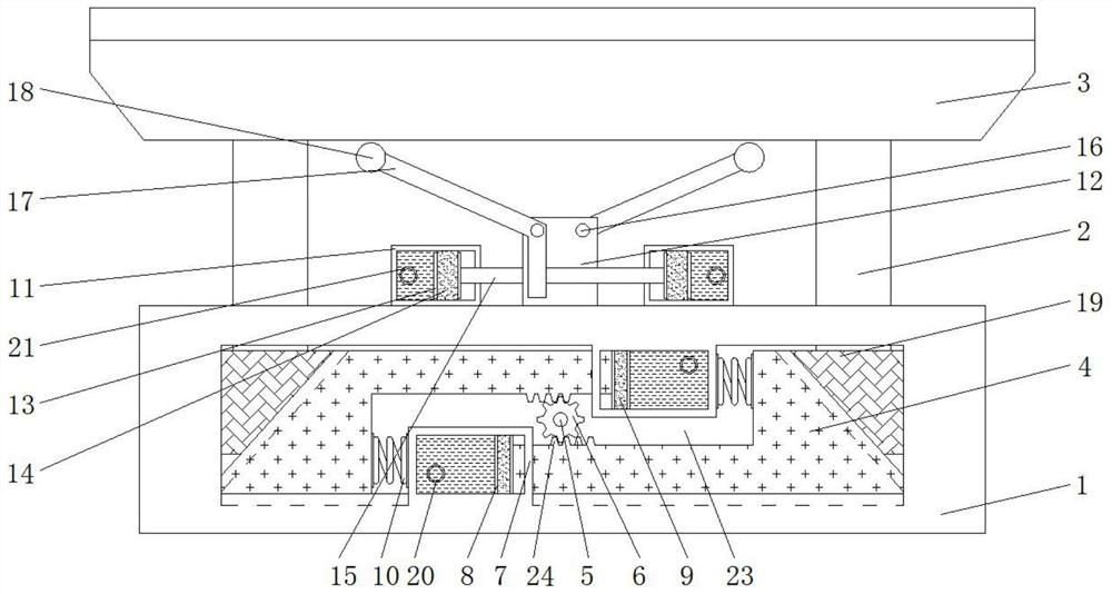
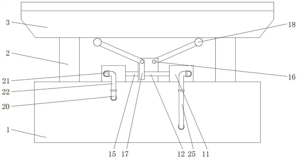
[0020] see Figure 1-2 , an embodiment provided by the present invention: a steel-concrete composite beam, comprising a base 1, both sides of the bottom of the inner wall of the base 1 are slidingly connected to a transmission seat 4, and one of the two transmission seats 4 is separated from each other. The side is slidingly connected with a sliding seat 19, and the tops of the two sliding seats 19 are fixedly connected with steel beams 2, and the tops of the ...


PUM


Abstract

The invention discloses a steel-concrete composite beam which comprises a base, transmission bases are slidably connected to the two sides of the bottom of the inner wall of the base, sliding bases are slidably connected to the sides, away from each other, of the two transmission bases, steel beams are fixedly connected to the tops of the two sliding bases, and the tops of the two steel beams penetrate through the base and extend to the upper portion of the base. By pushing the transmission base on the left side rightwards, teeth in the rectangular groove in the transmission seat also move rightwards along with the transmission seat, so that the gear is driven to rotate, the teeth below the gear are driven to move rightwards, the other transmission seat is driven to move rightwards from the left side of the base, and the supporting point at the bottom of the sliding base on the other side is lowered; the top of the right sliding seat is stressed by the other steel beam and the right side of the concrete plate, so that the right sliding base slides downwards, the two sides of the concrete plate are balanced, the self-adjusting balance performance of the steel-concrete composite beamis improved, the situation that the composite beam is broken due to the fact that one end is stressed to incline is prevented, and the service life of the steel-concrete composite beam is prolonged.

Description

technical field [0001] The invention relates to the technical field of composite beams, in particular to a steel-concrete composite beam. Background technique [0002] Steel-concrete composite beam is a new type of structure developed on the basis of steel structure and concrete structure. It mainly resists the lifting and relative slippage at the interface between the steel beam and the concrete flange plate by setting shear connectors (bolts, channel steel, bending bars, etc.), making it a whole work together. [0003] At present, the existing steel-concrete composite beams fix the steel beam and the concrete slab together through shear connectors. When one side of the top of the concrete slab is tilted under force, if it cannot be adjusted and reset, the force will be applied for a long time, which will cause the steel beam Cracks are generated at the connection with the concrete slab, which is more likely to cause breakage and safety accidents for a long time. The stab...

Claims


Application Information

Patent Timeline
IPC IPC(8): E01D19/00
CPCE01D19/00
Inventor 郭吉平韩洪举杨光华冉茂学张基进罗三张勇
Owner GUIZHOU ROAD & BRIDGE GRP
Why Eureka
Try Eureka