A kind of texturing equipment for dty glossy super soft flat yarn
A flat wire and equipment technology, applied in the field of DTY bright and super-soft flat wire texturing equipment, can solve the problems of easily damaged twisted yarn, small detection range, poor twisted yarn elasticity, etc., to avoid damage, improve detection and efficiency. The effect of processing efficiency
- Summary
- Abstract
- Description
- Claims
- Application Information
AI Technical Summary
Problems solved by technology
Method used
Image
Examples
Embodiment 1
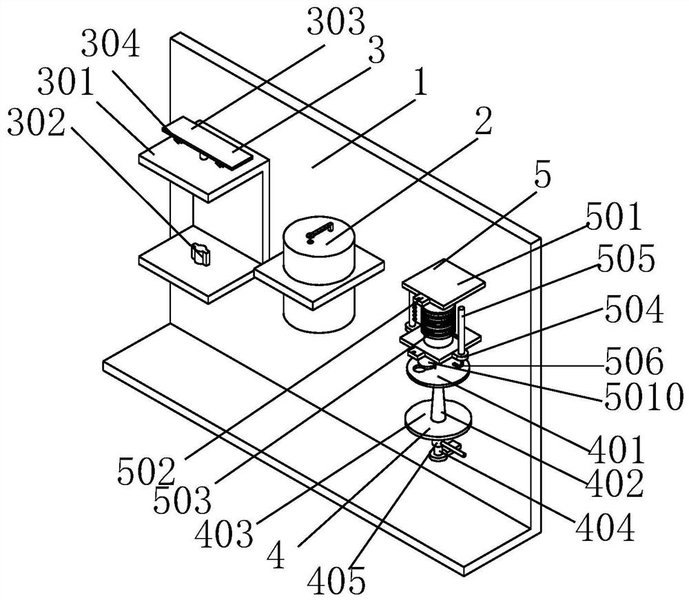
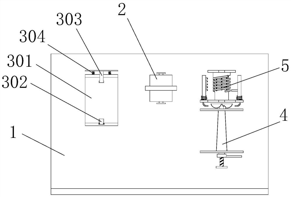
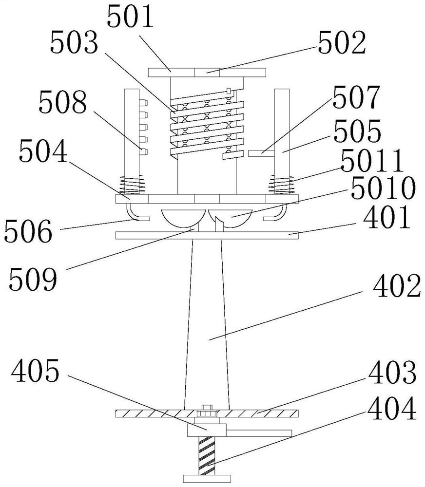
[0040] Example 1: Please refer to Figure 1-3 , a kind of texturing equipment for DTY glossy super soft flat yarn, comprising a frame 1, the front of the frame 1 is fixedly equipped with a false twist mechanism 2, a feeding mechanism 3, a feeding mechanism 4 and a detection mechanism 5, the feeding mechanism 3 is arranged on the left side of the frame 1, the unloading mechanism 4 is arranged on the right side of the frame 1, the false twisting mechanism 2 is arranged between the feeding mechanism 3 and the unloading mechanism 4, and the false twisting mechanism 2 is a prior art known technology. This will not go into details. The detection mechanism 5 is arranged above the feeding mechanism 4. The detection mechanism 5 includes a detection column 501. The shape of the detection column 501 is an I-shaped body. The top and bottom ends of the front of the detection column 501 are fixedly connected with wire blocks. 502, the bottom end of the middle part of the detection column 50...
Embodiment 2
[0042] Example 2: Please refer to Figure 4-5 , on the basis of Embodiment 1, a wire feeding mechanism 6 is provided on the wire block 502 below, and the wire feeding mechanism 6 includes a wire feeding cylinder 601, and a groove is opened on the top surface of the detection column 501 below, and the rotating bearing and the wire feeding mechanism 6 are arranged in the groove. The wire barrel 601 is fixedly connected. The wire feeding barrel 601 is T-shaped and the top surface is hollowed out. The inner wall on the left side of the top of the wire feeding barrel 601 is fixedly connected with the insertion rod 602. The outer wall is provided with a spiral groove and is in a nested relationship with the insertion rod 602. The top surface of the insertion rod 603 is fixedly connected with a connecting rod 604. The end of the connecting rod 604 far away from the insertion rod 603 is fixedly connected with the telescopic column 505. The middle part of the front of the wire feeding c...
Embodiment 3
[0043] Example 3: Please refer to Figure 6-7 , on the basis of Embodiment 2, the inside of the detection column 501 is in a hollow state and is inserted with a piston A9, the bottom surface of the piston A9 is fixedly connected with a spring C8, the outer wall of the connecting rod 604 is fixedly connected with a connecting rope 7, and the connecting rope 7 is far away from the wire feeding One end of the cylinder 601 runs through the detection column 501 and is fixedly connected with the piston A9. The interior of the upper half of the spiral ring 503 is hollowed out and the air hole A12 is laid on the top surface. The setting of the wire feeding mechanism 6, when the connecting rod 604 rises and falls with the telescopic column 505, the connecting rod 604 pulls the piston A9 through the connecting rope 7, and the piston A9 rises and falls reciprocally through the pulling of the connecting rope 7 and the rebound of the spring C8, And the air in the detection column 501 is sq...
PUM
 Abstract
Description
Claims
Application Information
 - R&D
- Intellectual Property
- Life Sciences
- Materials
- Tech Scout
- Unparalleled Data Quality
- Higher Quality Content
- 60% Fewer Hallucinations
Browse by: Latest US Patents, China's latest patents, Technical Efficacy Thesaurus, Application Domain, Technology Topic, Popular Technical Reports.
© 2025 PatSnap. All rights reserved.Legal|Privacy policy|Modern Slavery Act Transparency Statement|Sitemap|About US| Contact US: help@patsnap.com


