Carbon/carbon crucible and manufacturing method thereof

A technology for crucibles and prefabricated bodies, applied in crucibles, crucible furnaces, chemical instruments and methods, etc., can solve problems such as poor integrity of crucibles, damaged connection structures, and parts falling apart, so as to avoid waste of raw materials, reduce costs, and improve overall performance. Effect

Active Publication Date: 2021-02-09
XIAN CHAOMA SCI TECH
View PDF15 Cites 4 Cited by
  • Summary
  • Abstract
  • Description
  • Claims
  • Application Information

AI Technical Summary

Problems solved by technology

However, because the crucible is completely connected by mechanical structure, the integrity of the crucible is poor, and it is easy to be eroded during use, resulting in damage to the connection structure, which will cause the parts of the crucible to fall apart and lose their effectiveness.

Method used


Image

  • Carbon/carbon crucible and manufacturing method thereof
  • Carbon/carbon crucible and manufacturing method thereof
  • Carbon/carbon crucible and manufacturing method thereof

Examples


Embodiment 1

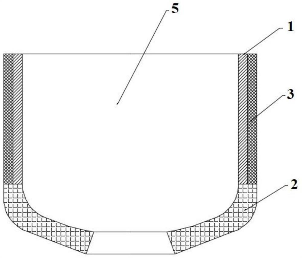
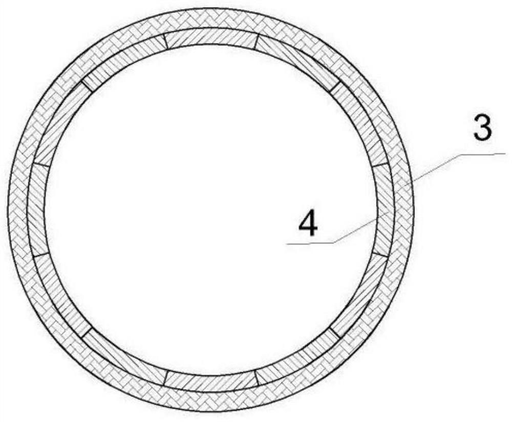
[0040] Such as figure 1 with figure 2 As shown, the first charcoal / charcoal crucible of this embodiment is composed of a crucible inner layer 1 and a crucible outer layer 3 that surrounds and covers part of the outer surface of the crucible inner layer 1. The crucible inner layer 1 is composed of a crucible bottom 2 It is assembled with 14 crucible petals 4, and the surrounding centers of the 14 crucible petals 4 are located on the axis line of the carbon / charcoal crucible, and the crucible bottom 2 and the 14 crucible petals 4 form an accommodation cavity 5, and the inside of the crucible The materials of layer 1 and outer layer 3 of the crucible are both carbon / carbon composite materials.

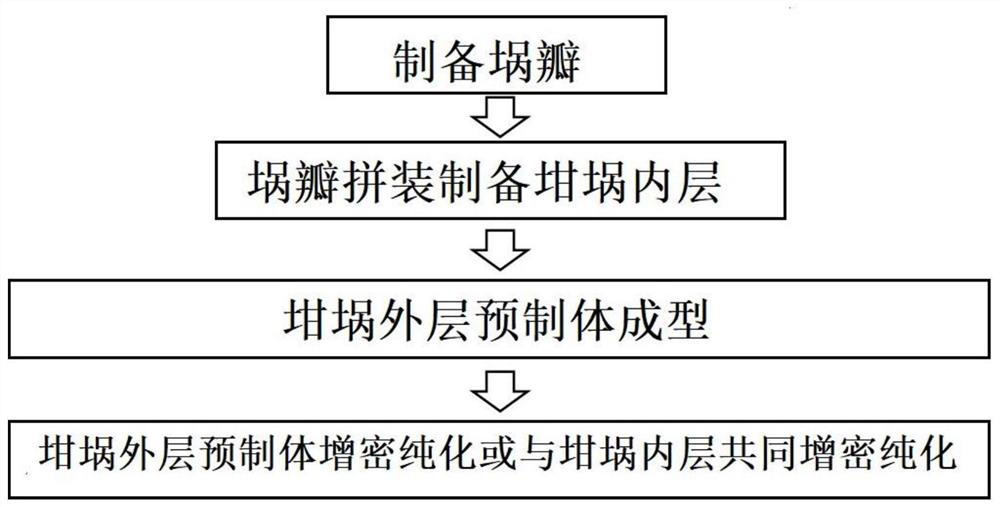
[0041] Such as image 3 with Figure 4 Shown, the concrete manufacturing process of first kind of charcoal / charcoal crucible of the present invention is:

[0042] Step 1. Choose a density greater than 1.3g / cm 3 The square material machine adds a long plate with a bevel on the side t...

Embodiment 2

[0053] Such as Figure 5 with Image 6 As shown, the second charcoal / charcoal crucible of the present invention is composed of a crucible inner layer 1 and a crucible outer layer 3 covering the outer surface of the crucible inner layer 1, and the crucible inner layer 1 is composed of three crucible flaps 4 assembled, 4 The surrounding center of the crucible petals 4 is located on the axis of the crucible, and the three crucible petals 4 form an accommodating cavity 5, and the materials of the crucible inner layer 1 and the crucible outer layer 3 are carbon / carbon composite materials, so The central angles corresponding to the circular arcs of the cross section of the crucible flap 4 along the horizontal direction are all 120°.

[0054] The concrete manufacturing process of second kind of charcoal / charcoal crucible of the present invention is:

[0055] Step 1. Select the petal-shaped profiling blank of carbon / carbon composite material to obtain the crucible petal 4 through ma...


PUM

PropertyMeasurementUnit
tensile strengthaaaaaaaaaa
densityaaaaaaaaaa
tensile strengthaaaaaaaaaa

Abstract

The invention discloses a carbon/carbon crucible. The carbon/carbon crucible is composed of a crucible inner layer and a crucible outer layer covering the outer surface of the crucible inner layer, wherein the crucible inner layer is formed by splicing a plurality of crucible petals, or is formed by splicing a crucible bottom and a plurality of crucible petals; and the crucible inner layer and thecrucible outer layer are both made of carbon/carbon composite materials. The invention further discloses a manufacturing method of the carbon/carbon crucible. The whole crucible inner layer or a partof the crucible inner layer of the carbon/carbon crucible is of a split structure, so the utilization rate of equipment required by crucible preparation is greatly increased, raw material waste is avoided, the production efficiency of the crucible is improved, the manufacturing cost of the crucible is reduced; and meanwhile, the outer surface of the crucible inner layer is covered with the crucible outer layer which is rapidly prepared and formed and serves as a reinforcing layer, so the circumferential structural strength and the mechanical properties of the crucible are improved, the erosion resistance of the crucible is improved, and the service life of the crucible is prolonged. The manufacturing method is simple in process and easy to implement.

Description

technical field [0001] The invention belongs to the field of composite material preparation, and in particular relates to a carbon / carbon crucible and a manufacturing method thereof. Background technique [0002] The crucible is an important part of a chemical instrument. It is a container for melting and refining metals, silicon materials, etc., as well as solid-liquid heating and reaction, and is the basis for ensuring the smooth progress of chemical reactions. Take the crucible for single crystal Czochralski as an example. Now the line width of integrated circuits has entered the nanometer era. The larger the diameter of silicon wafers, the more integrated circuits that can be engraved, and the lower the cost of chips. With the rapid increase in demand and size, the market demand for monocrystalline silicon rods is also showing a trend of rapid growth. [0003] According to different crystal growth methods, single crystal silicon can be divided into Czochralski method (...

Claims


Application Information

Patent Timeline
Patent Type & Authority Applications(China)
IPC IPC(8): C04B35/83C04B35/532F27B14/10B01L3/04C30B13/14C30B15/10C30B19/06
CPCC04B35/83C04B35/532F27B14/10B01L3/04C30B15/10C30B13/14C30B19/067F27B2014/102C04B2235/5248C04B2235/612C04B2235/96
Inventor 程皓张灵玉赵松闵明康文杰党瑞萍王晶晶邢如鹏侯卫权孟凡才
Owner XIAN CHAOMA SCI TECH
Why Eureka
Try Eureka