
Rail self-propelled electrostatic mist sprayer

A mist mist machine and self-propelled technology, which is applied in electrostatic spraying devices, greenhouse cultivation, climate change adaptation and other directions, can solve the problems that the atomizing device cannot achieve spraying in small areas, needs manual cooperation, and the spraying is not uniform enough, and can increase the number of sprays. Mist mist efficiency, rapid operation, and the effect of improving mist mist efficiency

Pending Publication Date: 2021-02-09
WEIFANG UNIV OF SCI & TECH +1
View PDF3 Cites 1 Cited by
  • Summary
  • Abstract
  • Description
  • Claims
  • Application Information

AI Technical Summary

Problems solved by technology

Patent CN209965054U has designed a mist mist device that uses ozone water atomization to sterilize. The device is designed with a walking frame and an electrostatic nozzle to realize mobile spraying. It is impossible to spray small areas, resulting in a large waste of cost, so it is impossible to spray greenhouse crops; patent CN203556498U has designed a wind, gas and static electricity combined traction fog machine, which uses the wind curtain wall to make the liquid carry out two The secondary atomization plays a role in preventing the droplets from escaping. At the same time, the device adopts an electrostatic generating device to improve the adsorption of the liquid medicine. The nozzle of the machine cannot rotate in a large range, resulting in uneven spraying; patent CN102318593A designs a mist misting machine with a gantry spray rack, which can cover the entire fruit tree for spraying, and the nozzle is designed as a syncline Spraying medicine at the rear avoids spraying medicine on people, but the gantry nozzle of the device cannot carry out partial spraying and spraying in different directions, resulting in a lot of waste of materials. The adsorption is also poor

Method used


Image

  • Rail self-propelled electrostatic mist sprayer
  • Rail self-propelled electrostatic mist sprayer
  • Rail self-propelled electrostatic mist sprayer

Examples


Embodiment Construction

[0033] The technical solutions in the embodiments of the present invention will be clearly and completely described below in conjunction with the drawings in the present invention. Apparently, the described embodiments are only some of the embodiments of the present invention, not all of them. Based on the embodiments of the present invention, all other embodiments obtained by persons of ordinary skill in the art without making creative efforts belong to the protection scope of the present invention.

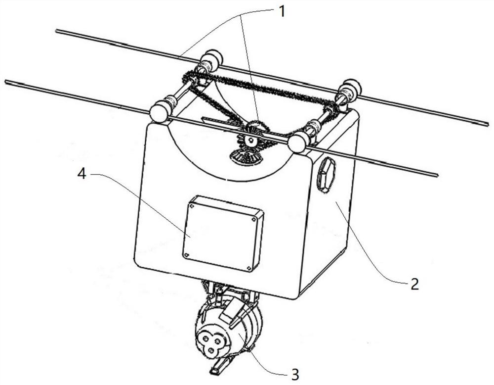
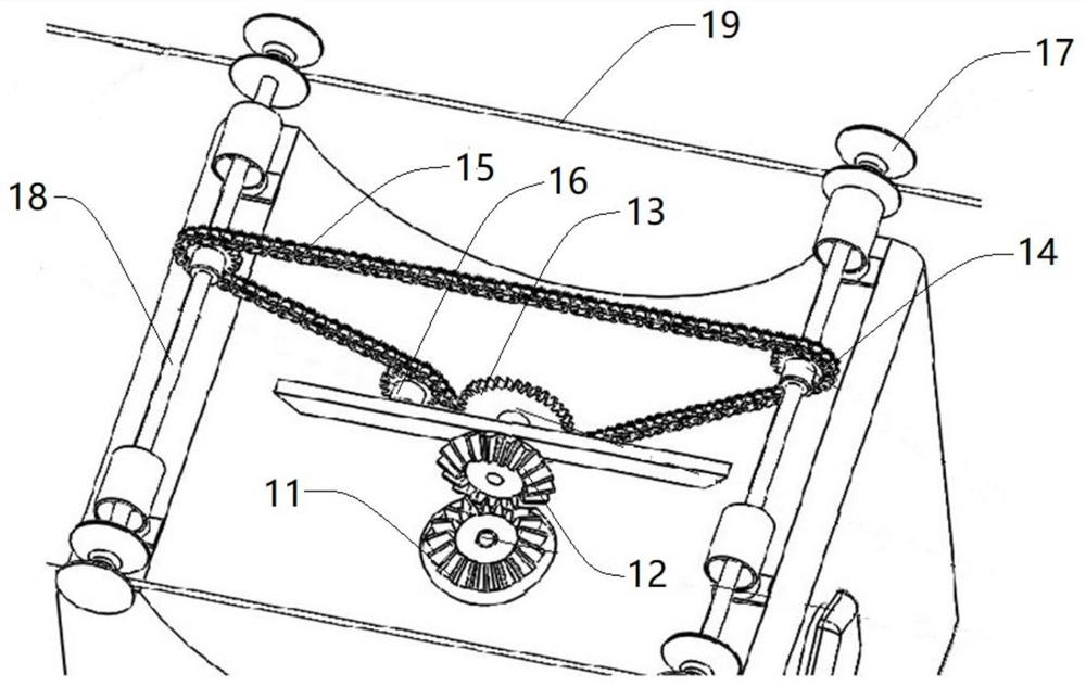
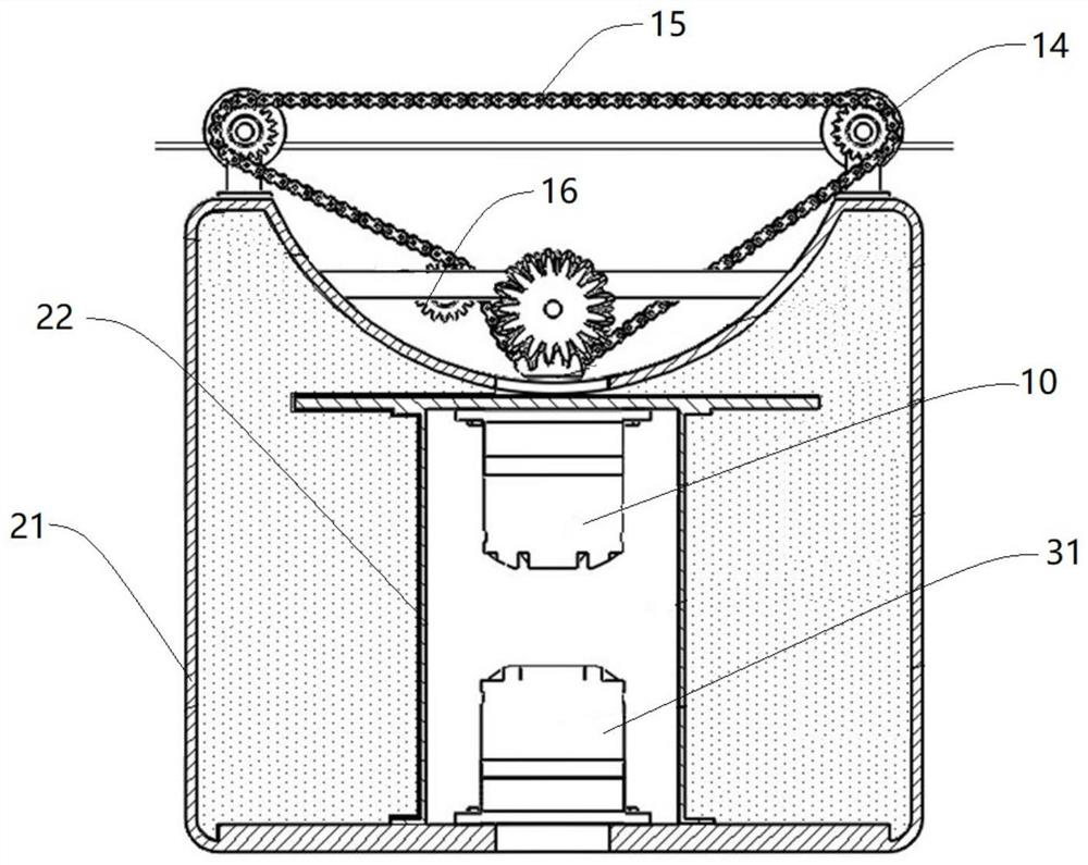
[0034] like figure 1 As shown, a track self-propelled electrostatic mist misting machine of the present invention includes a self-propelled device 1, a liquid storage device 2 located below the self-propelled device 1, and a mist mist device 3 located below the liquid storage device 2, wherein the self-propelled The device 1 is used to realize unmanned spraying, the liquid storage device 2 is the main structure of the mist mist machine, located in the middle of the mist mist mac...


PUM


Abstract

The invention belongs to the technical field of spraying equipment, and particularly relates to a rail self-propelled electrostatic mist sprayer. The mist sprayer comprises an automatic walking device, a liquid storage device located below the automatic walking device and a mist spraying device located below the liquid storage device. The automatic walking device comprises a first motor, a transmission assembly connected with the first motor and a guide rail in rolling connection with the transmission assembly, and the first motor is fixed in the liquid storage device; the mist spraying devicecomprises a second motor, a rotary controller connected with the second motor and a mist spraying assembly connected with the second motor, and the second motor is fixed in the liquid storage device;and an electrostatic generator is mounted below the mist spraying assembly. The rail self-propelled electrostatic mist sprayer is simple in structure and complete in function, has the suspension typerail self-walking function, achieves unmanned spraying and all-around spraying, and has the electrostatic adsorption capacity of fog drops.

Description

technical field [0001] The invention belongs to the technical field of spray equipment, in particular to a track self-propelled electrostatic mist diffuser. Background technique [0002] As an atomization and spraying device for pesticides and other liquids, the mist mist machine is widely used in agricultural fruit and vegetable gardens and public health occasions. In particular, the application of pesticide spraying of crops, pest control, dehumidification and humidification of vegetable greenhouses, and foliar supplementation is more common. In recent years, with the continuous development of modern agriculture, my country's agricultural structure is also constantly adjusted, and the demand for agricultural mechanization becomes more urgent. [0003] Relevant patents or papers at home and abroad have proposed a variety of design schemes for misting machines. Patent CN209965054U has designed a mist mist device that uses ozone water atomization to sterilize. The device is...

Claims


Application Information

Patent Timeline
IPC IPC(8): A01M7/00A01C23/04A01C23/00A01G9/24B05B5/00B05B7/02B05B7/08B05B15/00
CPCA01C23/007A01C23/047A01G9/247A01M7/0042A01M7/005A01M7/0089B05B5/00B05B7/02B05B7/08B05B15/00Y02A40/25
Inventor 闫洋洋韩建新马军韩丙宝王玉端魏楫王晓洁刘炳强
Owner WEIFANG UNIV OF SCI & TECH
Learn More