Loudspeaker heat dissipation protection equipment

A protective device and speaker technology, applied in the field of speakers, can solve problems affecting the sound quality and service life of speakers, internal circuit damage, and coil electrode connections fall off, etc., to prevent dust from entering the speaker, avoiding impact, and avoiding damage.

Inactive Publication Date: 2021-02-05
深圳市天同玩具有限公司
View PDF0 Cites 0 Cited by
  • Summary
  • Abstract
  • Description
  • Claims
  • Application Information

AI Technical Summary

Problems solved by technology

[0002] In our daily life, speakers are often used for volume diffusion. When the speakers work at high power for a long time, they are stored in a closed space, which is not conducive to heat dissipation, which will affect the sound quality and service life of the speakers. Traditional speakers generally dissipate heat. The heat dissipation fan and water cooling are used to cool down. When the traditional heat dissipation fan guides the air flow, it will transport the moisture and dust from the outside to the inside of the speaker, which will easily cause damage and short circuit of the internal circuit. The traditional water cooling method, in the pipe connection Leakage at the place of the speaker will easily cause a short circuit, which will affect the service life of the speaker. The reciprocating movement of the voice coil of the traditional speaker will easily cause the connection of the coil electrode to fall off, which will affect the work of the speaker. A speaker heat dissipation protection device described in the present invention can solve the problem. above question

Method used


Image

  • Loudspeaker heat dissipation protection equipment
  • Loudspeaker heat dissipation protection equipment
  • Loudspeaker heat dissipation protection equipment

Examples


Embodiment Construction

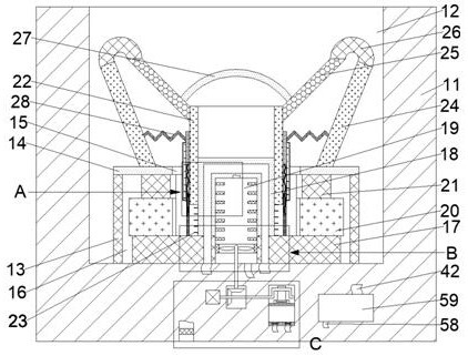
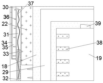
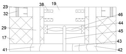
[0016] Combine below Figure 1-4 The present invention is described in detail, wherein, for the convenience of description, the orientations mentioned below are defined as follows: figure 1 The up, down, left, right, front and back directions of the projection relationship itself are the same.

[0017] A loudspeaker heat dissipation protection device according to the present invention includes a body 11, the upper end of the body 11 is communicated with a working chamber 12 with an upward opening, and the lower wall of the working chamber 12 is fixed with an upwardly extending magnet protection cover 13, The upper end surface of the magnet protection cover 13 is fixedly provided with a closing plate 14, and a moving hole 15 is connected between the upper and lower end surfaces of the closing plate 14, and a storage chamber is arranged between the closing plate 14 and the magnet protection cover 13. 16. The lower wall of the storage chamber 16 is fixed with a lower magnetic gu...


PUM


Abstract

The invention discloses loudspeaker heat dissipation protection equipment. The loudspeaker heat dissipation protection equipment comprises a machine body, wherein a working cavity with an upward opening is formed in the upper end face of the machine body in a communicating mode, a magnet protection cover extending upwards is fixedly arranged on the lower wall face of the working cavity, and a closing plate is fixedly arranged on the upper end face of the magnet protection cover. According to the invention, heat dissipation processing is carried out on the loudspeaker which operates at high power for a long time, the sound quality and the service life of the loudspeaker can be effectively prevented from being influenced by heat accumulation of the voice coil during operation, and external dust is effectively prevented from entering the loudspeaker by utilizing a mode of combining air cooling and water cooling. Meanwhile, the device can reduce the damage to equipment caused by water leakage, effectively avoids the breakage of the electrodes caused by the up-and-down high-frequency vibration of the voice coil through the isolation protection of the coil electrodes and provides a goodenvironment for the operation of the loudspeaker. The device also can fix the lateral position of the voice coil, and therefore, the influence of high-frequency vibration on the position of the voicecoil can be avoided.

Description

technical field [0001] The invention relates to the field of loudspeakers, in particular to a loudspeaker heat dissipation protection device. Background technique [0002] In our daily life, speakers are often used for volume diffusion. When the speakers work at high power for a long time, they are stored in a closed space, which is not conducive to heat dissipation, which will affect the sound quality and service life of the speakers. Traditional speakers generally dissipate heat. The heat dissipation fan and water cooling are used to cool down. When the traditional heat dissipation fan guides the air flow, it will transport the moisture and dust from the outside to the inside of the speaker, which will easily cause damage and short circuit of the internal circuit. The traditional water cooling method, in the pipe connection Leakage at the place of the speaker will easily cause short-circuiting of the line, which will affect the service life of the speaker. The reciprocatin...

Claims


Application Information

Patent Timeline
Patent Type & Authority Applications(China)
IPC IPC(8): H04R9/06H04R9/02
CPCH04R9/022H04R9/06H04R2209/00
Inventor 胡吴红
Owner 深圳市天同玩具有限公司
Why Eureka
Try Eureka