Part quenching cooling line

A technology for cooling lines and parts, applied in the field of quenching and processing of metal parts, can solve the problems of increasing energy cost, worrying about feeding operators, and spreading to the feeding level, etc., and achieve the effect of saving energy use and maintenance cost.

Inactive Publication Date: 2021-02-05
嘉善奥力科机械制造有限公司
View PDF4 Cites 0 Cited by
  • Summary
  • Abstract
  • Description
  • Claims
  • Application Information

AI Technical Summary

Problems solved by technology

According to different heating methods, it can be divided into induction heating surface quenching, flame heating surface quenching, electric contact heating surface quenching, electrolyte heating surface quenching, etc. Existing quenching furnaces generally use some gas, but the amount of gas is too much Or too little will cause problems, and the temperature of the quenching furnace will spread to the feeding position, which will cause troubles to the loading operator and affect the feeding efficiency; parts are generally cleaned after quenching and cooling, and hot water is generally used for cleaning The effect is better, but heating the water alone will increase the energy cost; the bearing seat on the transportation line in the existing quenching furnace is prone to deformation in a long-term high-temperature environment, making the transportation of the transportation line unsmooth

Method used


Image

  • Part quenching cooling line
  • Part quenching cooling line
  • Part quenching cooling line

Examples


Embodiment Construction

[0020] In order to make the technical means, creative features, goals and effects achieved by the present invention easy to understand, the present invention will be further elaborated below in conjunction with illustrations and specific embodiments.

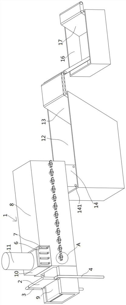
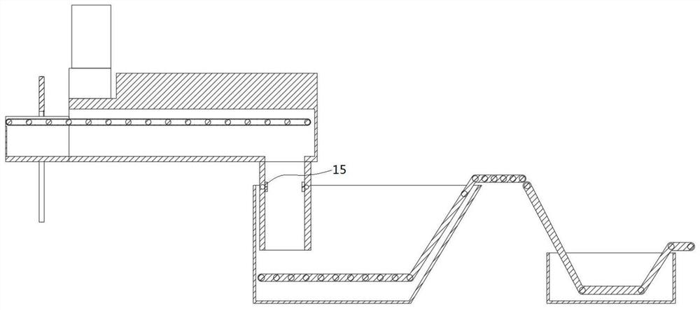
[0021] Such as Figure 1 to Figure 3 As shown, a kind of part quenching cooling line that the present invention proposes comprises mesh belt quenching furnace 1; The discharge end of described mesh belt quenching furnace 1 is provided with cooling device, and the discharge end of described cooling device is provided with cleaning device, so The feeding end of the mesh belt quenching furnace 1 is provided with a heating device utilizing the temperature of the mesh belt quenching furnace for heating, and a heat shield mechanism and a gas control mechanism are also arranged between the feeding ends of the mesh belt quenching furnace 1, so that The heat-shielding mechanism includes a heat-shielding plate 2 with a water storage chamb...


PUM


Abstract

The invention relates to a part quenching cooling line which comprises a mesh belt quenching furnace. A cooling device is arranged at the discharge end of the mesh belt quenching furnace; a cleaning device is arranged at the discharge end of the cooling device; a heating device for heating by utilizing the temperature of the mesh belt quenching furnace is arranged at the feed end of the mesh beltquenching furnace; and a heat shielding mechanism and a gas control mechanism are further arranged between the feed end of the mesh belt quenching furnace. According to the part quenching cooling lineprovided by the invention, through the arrangement of the heat shielding mechanism, the temperature in the mesh belt quenching furnace cannot be transferred to an inlet of the mesh belt quenching furnace, so that the feeding efficiency of an operator cannot be influenced; according to the cooling line, through the arrangement of the gas control mechanism, the content of methanol and propane in the mesh belt quenching furnace can be observed; when the content is lower than a set value, atmosphere controllers can switch on corresponding electronic valves, so that corresponding gas is added; andaccording to the cooling line, water is heated through the heating mechanism by using heat of the mesh belt quenching furnace and then conveyed to the cleaning device so as to be utilized, so that energy is saved.

Description

technical field [0001] The invention relates to the field of quenching processing of metal parts, in particular to a quenching and cooling line for parts. Background technique [0002] Quenching is a surface heat treatment process that quenches the surface of steel workpieces. The purpose is to improve the hardness, wear resistance and fatigue strength of the workpiece surface, while the core still has high toughness. Commonly used in shafts, gears and other parts. During the operation, the surface layer of the workpiece is austenitized by rapid heating, and then quenched immediately to transform the surface layer into martensite, and the core structure remains basically unchanged. Low temperature tempering is generally carried out after surface quenching. According to different heating methods, it can be divided into induction heating surface quenching, flame heating surface quenching, electric contact heating surface quenching, electrolyte heating surface quenching, etc...

Claims


Application Information

Patent Timeline
Patent Type & Authority Applications(China)
IPC IPC(8): C21D1/62C21D1/74C21D9/00C21D11/00
CPCC21D1/62C21D1/74C21D9/0018C21D11/00
Inventor 钱忠钱建春
Owner 嘉善奥力科机械制造有限公司
Why Eureka
Try Eureka