
A kind of multifunctional magnetic separator for polyamide production

A multi-functional, polyamide technology, applied in the direction of magnetic separation, cleaning methods and tools, cleaning methods using tools, etc., can solve the problems of inability to separate non-metallic particles from water, restrict production efficiency, consume large water and electricity, etc. Achieve the effects of rich and practical functions, simplified complex structures, and reduced manufacturing costs

Active Publication Date: 2021-07-23
山东宝泰隔热材料有限公司
View PDF13 Cites 0 Cited by
  • Summary
  • Abstract
  • Description
  • Claims
  • Application Information

AI Technical Summary

Problems solved by technology

[0002] During the production of polyamide, it is necessary to separate and remove the iron filings generated by the reaction in the raw material mixture. At present, wet magnetic separators are mostly used for iron filing separation. The existing wet magnetic separator absorbs iron filings on the rotating drum, and then passes through The high-pressure water gun falls down into the chip flute to complete the separation, and the solution without iron filings flows from the other side to the drain port to the next sequence. The existing wet magnetic separator uses a high-pressure water gun to consume a lot of water and electricity. It can separate iron filings in the solution, but cannot separate non-metallic particles from water. In addition, many non-metallic particles will not flow to the drain with the solution. Users need to clean the inside of the magnetic separator regularly, which restricts production efficiency.

Method used


Image

  • A kind of multifunctional magnetic separator for polyamide production
  • A kind of multifunctional magnetic separator for polyamide production

Examples


Embodiment Construction

[0013] In order to make the purpose, technical solutions and advantages of the embodiments of the present invention clearer, the technical solutions in the embodiments of the present invention will be clearly and completely described below in conjunction with the drawings in the embodiments of the present invention. Obviously, the described embodiments It is a part of embodiments of the present invention, but not all embodiments. Based on the embodiments of the present invention, all other embodiments obtained by persons of ordinary skill in the art without creative efforts fall within the protection scope of the present invention.

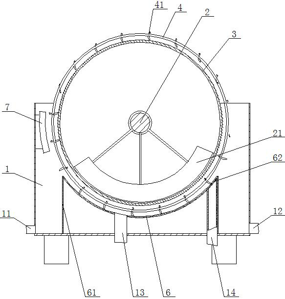
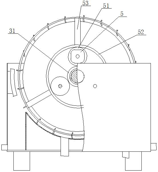
[0014] A multifunctional magnetic separator for polyamide production, as shown in the figure, includes a box body 1 with an open top, and a fixed shaft 2 is arranged longitudinally inside the box body 1, and the front and rear ends of the fixed shaft 2 are respectively corresponding to the side walls of the box body 1 Fixed connection, the arc mag...


PUM


Abstract

A multifunctional magnetic separator for polyamide production. The invention belongs to the field of polyamide production. It includes a box with an open top. A fixed shaft is arranged longitudinally in the box. The front and rear ends of the fixed shaft are respectively fixedly connected to the corresponding side walls of the box. An arc-shaped magnet is fixed under the fixed shaft, and a coaxial roller is set on the outside of the fixed shaft. There is a through groove on the side of the arc-shaped plate away from the magnet block. The lower end of the through groove is fixedly connected to the upper end of the drain pipe, and the drain pipe passes downward Cabinet bottom plate. This device realizes the simultaneous separation of iron filings and non-magnetic solid particles in the liquid. Compared with the existing magnetic separator, the function is more abundant and practical. The whole device only needs to be driven by a motor, which simplifies the complexity of the existing wet magnetic separator that needs to be equipped with a high-pressure water gun. The structure reduces the manufacturing cost. Using the magnetic force of the magnetic separator itself, the scraper can not only hang and remove the iron filings on the drum, but also clean up the solid particles deposited on the top surface of the curved plate. It is suitable for polyamide promotion in the field of production.

Description

technical field [0001] The invention belongs to the field of polyamide production, in particular to a multifunctional magnetic separator for polyamide production. Background technique [0002] During the production of polyamide, it is necessary to separate and remove the iron filings generated by the reaction in the raw material mixture. At present, wet magnetic separators are mostly used for iron filing separation. The existing wet magnetic separator absorbs iron filings on the rotating drum, and then passes through The high-pressure water gun falls down into the chip flute to complete the separation, and the solution without iron filings flows from the other side to the drain port to the next sequence. The existing wet magnetic separator uses a high-pressure water gun to consume a lot of water and electricity. It can separate iron filings in the solution, but cannot separate non-metallic particles from water. In addition, many non-metallic particles will not flow to the dr...

Claims


Application Information

Patent Timeline
Patent Type & Authority Patents(China)
IPC IPC(8): B03C1/14B03C1/30B08B1/04B08B1/02
CPCB03C1/14B03C1/30B08B1/005B08B1/02B08B1/04
Inventor 蒋林熠
Owner 山东宝泰隔热材料有限公司
Learn More