Rotating speed self-adjusting type lithium battery cell slurry fluctuation type stirring equipment
A stirring equipment and self-regulating technology, which is applied in the direction of lithium batteries, mixers with rotating stirring devices, mixer accessories, etc., can solve the problems of energy loss, uneven mixing of electric core slurry, high labor intensity, etc., and achieve faster stirring Effect
- Summary
- Abstract
- Description
- Claims
- Application Information
AI Technical Summary
Problems solved by technology
Method used
Image
Examples
Embodiment 1
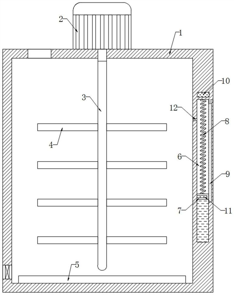
[0020] refer to figure 1 , a speed self-adjusting type lithium battery cell pulp wave stirring equipment, including a stirring box 1, the upper end of the stirring box 1 is fixedly connected with a motor 2, the movable end of the motor 2 runs through the upper end of the stirring box 1 and is fixedly connected with a rotating shaft 3, and the rotating shaft 3 The side wall is fixedly connected with a plurality of stirring rods 4, the inner bottom of the stirring box 1 is fixedly connected with a heating plate 5, the side wall of the stirring box 1 is provided with a sliding plug cavity 6, and the inner wall of the sliding plug cavity 6 is sealed and slidingly connected with a conductive plate 7, which needs to be explained What is more, there is a through hole above the inner wall of the sliding plug cavity 6 to balance the pressure change in the sliding plug cavity 6 when the conductive plate 7 slides, and the sealed space formed by the lower end of the conductive plate 7 and ...
Embodiment 2
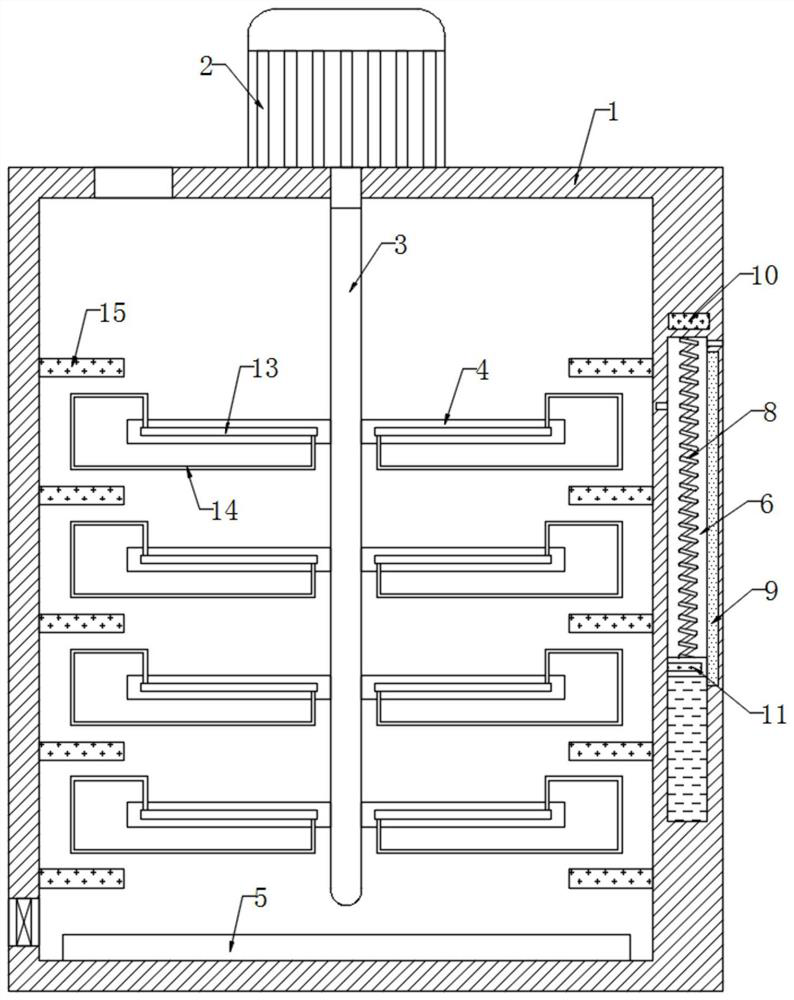
[0026] refer to figure 2 , different from Embodiment 1, the stirring rod 4 is embedded with a heating rod 13, the two ends of the heating rod 13 are coupled with a lead frame 14, the inner wall of the stirring box 1 is fixedly connected with a plurality of permanent magnet blocks 15, and a plurality of stirring rods 4 are respectively located between two adjacent permanent magnet blocks 15, and the relative magnetic poles of the two adjacent permanent magnet blocks 15 are opposite, so that a magnetic field loop is formed between the two permanent magnet blocks 15, and then the connection between the lead frame 14 and the magnetic induction line can be realized. cutting.
[0027] In this embodiment, when the stirring rod 4 rotates, the lead frame 14 is driven to continuously pass between the two permanent magnet blocks 15 fixedly connected to the inner wall of the stirring tank 1, and then the lead frame 14 continuously cuts the magnetic induction between the two permanent mag...
PUM
 Abstract
Description
Claims
Application Information
 - R&D
- Intellectual Property
- Life Sciences
- Materials
- Tech Scout
- Unparalleled Data Quality
- Higher Quality Content
- 60% Fewer Hallucinations
Browse by: Latest US Patents, China's latest patents, Technical Efficacy Thesaurus, Application Domain, Technology Topic, Popular Technical Reports.
© 2025 PatSnap. All rights reserved.Legal|Privacy policy|Modern Slavery Act Transparency Statement|Sitemap|About US| Contact US: help@patsnap.com


