Die-casting machine tool capable of achieving quick correction of position and used for security door machining
A technology for correcting position and anti-theft doors, applied in the field of die-casting machine tools for processing anti-theft doors, which can solve problems such as deviation, reduce stability, and material deflection
- Summary
- Abstract
- Description
- Claims
- Application Information
AI Technical Summary
Problems solved by technology
Method used
Image
Examples
Embodiment 1
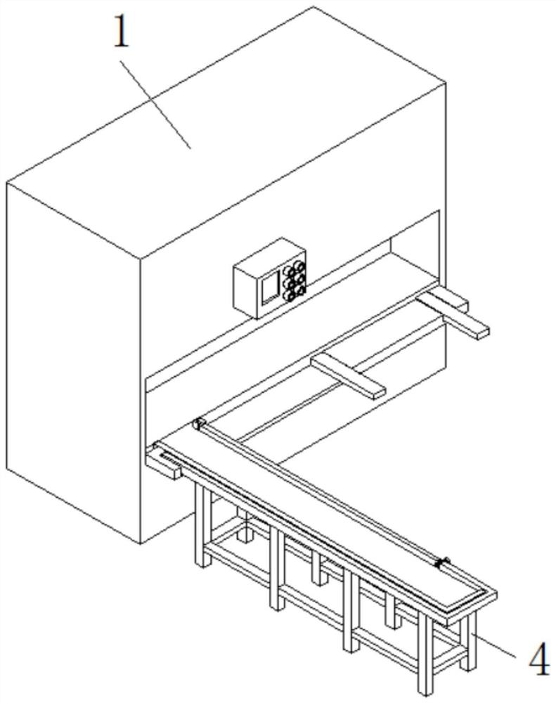
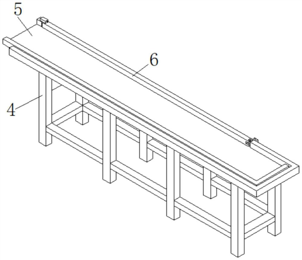
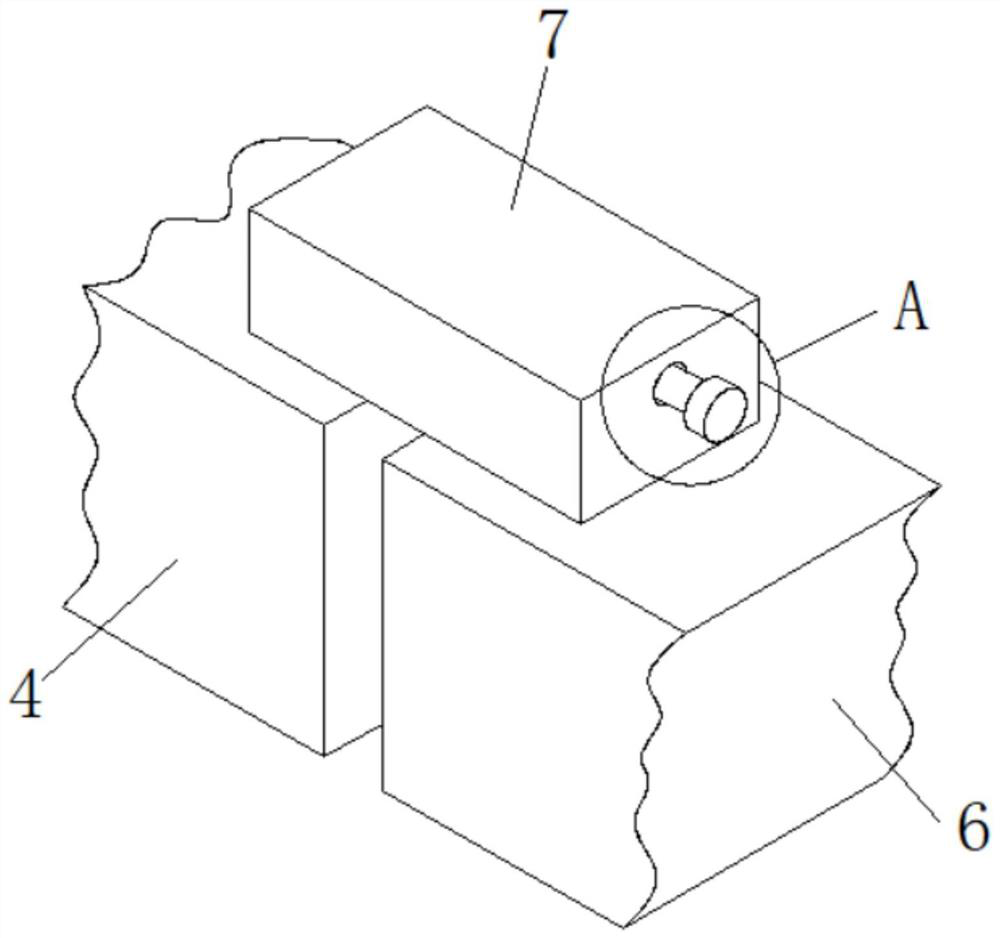
[0030]SeeFigure 1-8, A die-casting machine tool for processing anti-theft doors that can quickly correct positions, including a device body 1, a support frame 4 is fixedly connected to the front side of the device body 1, a sliding plate 5 is movably connected to the top of the support frame 4, and the inner wall of the support frame 4 The positioning rod 6 is movably connected, the right side of the top of the support frame 4 is fixedly connected to the housing 7, the inner wall of the housing 7 is fixedly connected to the limit sleeve 14, and the inner wall of the limit sleeve 14 is movably connected with the transmission mechanism 2 and the transmission mechanism 2. The rear side is fixedly connected to the inner wall of the housing 7, the front side of the transmission mechanism 2 penetrates to the front side of the housing 7, and the inner wall of the transmission mechanism 2 is movably connected to the limit mechanism 3, and both sides of the limit mechanism 3 are connected to...
Embodiment 2
[0034]SeePicture 9 A die-casting machine tool for processing anti-theft doors that can quickly correct positions further includes a transmission mechanism 2, wherein the transmission mechanism 2 includes a button 203, the rear side of the button 203 is fixedly connected with a movable rod 202, and the rear side of the movable rod 202 penetrates to the shell The inner cavity of the body 7 is fixedly connected with a spring 201, the rear side of the spring 201 is fixedly connected with the inner wall of the housing 7, and the inner wall of the movable rod 202 is movably connected with the surface of the limit mechanism 3. The transmission mechanism 2 is provided to facilitate the use When the user needs to rotate the positioning rod 6, the user can press the button 203 to disengage the limit rod 306 from the inner cavity of the limit hole 19, and the user can rotate the positioning rod 6 so that the positioning rod 6 guides the material to the sliding plate 5. A pulley 21 is fixedly c...
PUM
 Abstract
Description
Claims
Application Information
 - R&D Engineer
- R&D Manager
- IP Professional
- Industry Leading Data Capabilities
- Powerful AI technology
- Patent DNA Extraction
Browse by: Latest US Patents, China's latest patents, Technical Efficacy Thesaurus, Application Domain, Technology Topic, Popular Technical Reports.
© 2024 PatSnap. All rights reserved.Legal|Privacy policy|Modern Slavery Act Transparency Statement|Sitemap|About US| Contact US: help@patsnap.com


