


Quick Research
Generate reliable direction feasibility study reports for your R&D in just a few steps.

Technical Q&A
Discover and master advanced knowledge NOW. Basics, ideas, possibilities, all at once.

Find Solutions
As an expert in R&D theories, this can generate solutions to your technical problems instantly.

Evaluate Feasibility
Analyze your overall solution with one click, know your potential R&D risks in advance.

Monitor Landscape
Get weekly tech updates, stay abreast of the latest tech innovations and key insights.
Micro-fluidic valve and micro-fluidic chip
A technology of microfluidic chips and microvalves, applied in the field of microfluidics, can solve the problems of increasing the sealing steps of finished chips, poor sealing performance, cumbersome process, etc., and achieve the effects of ensuring stability, small deformation, and simple preparation process
- Summary
- Abstract
- Description
- Claims
- Application Information
AI Technical Summary
Problems solved by technology
Method used
Image

Examples
Embodiment 1
[0045] Example 1 A microfluidic control valve
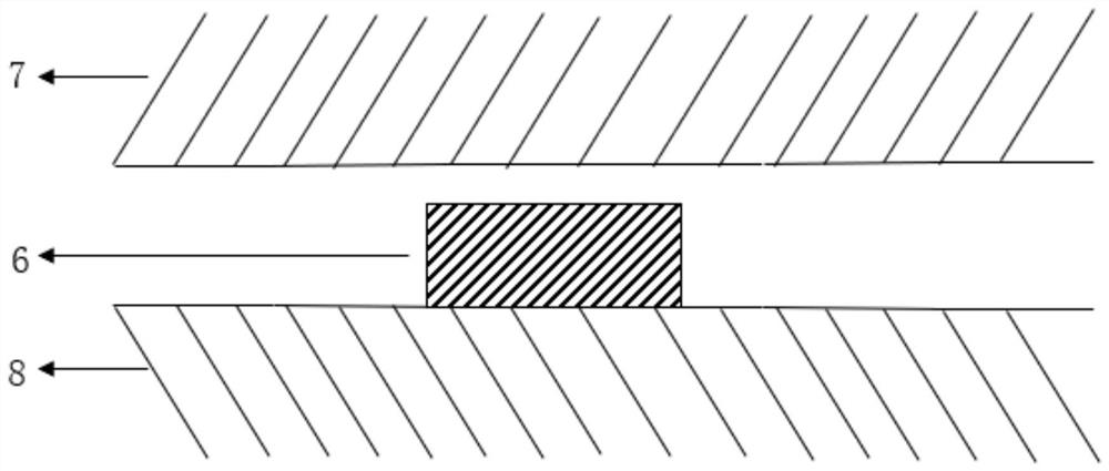
[0046] Including pipes and micro valves 6, one side 7 of the pipes is made of elastic materials such as pdms or transparent silicone, and the other side 8 of the pipes is made of hard materials such as pmma, resin materials, etc., and the two sides are bonded with double-sided tape.
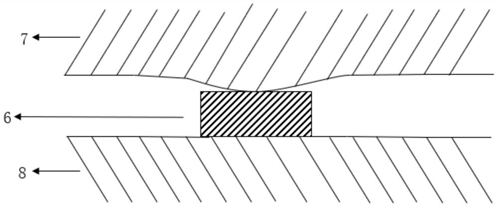
[0047] The microvalve 6 is located inside the pipeline and is cylindrical. The cross-sectional width of the microvalve 6 is equal to the width of the pipeline. One end of the microvalve is fixedly connected to the pipeline, and its height is 90% of the pipeline height. When the external force is applied, the other end of the microvalve 6 is in contact with the pipeline, and the pipeline is closed to realize the closure of the liquid in the pipeline. When the external force is removed, the liquid in the pipeline resumes its flow.
Embodiment 2
[0048] Example 2 A microfluidic chip
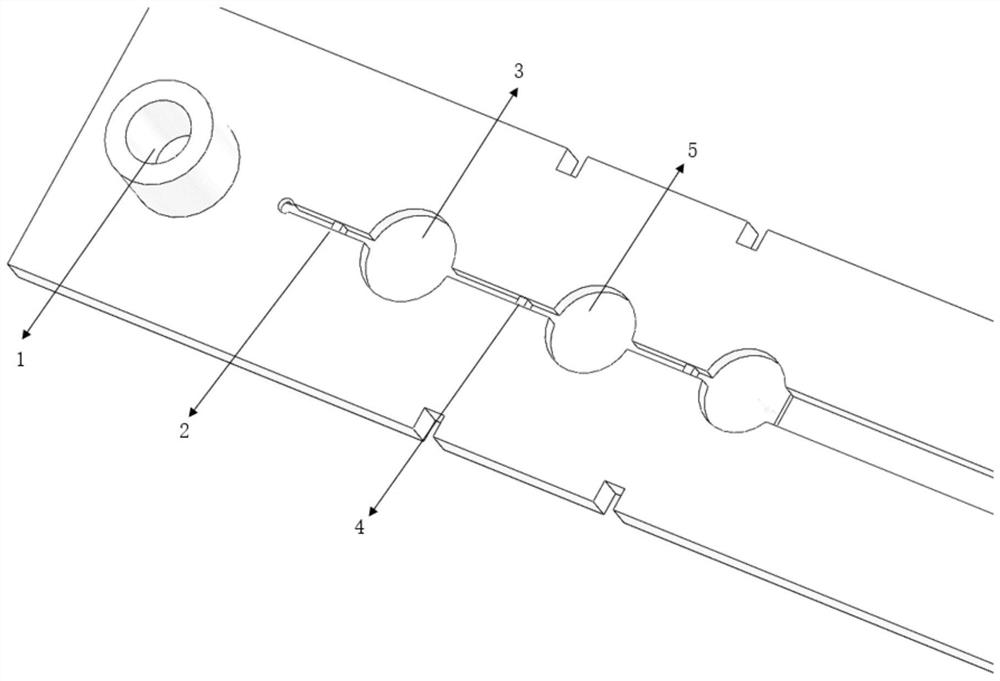
[0049] Such as image 3 As shown, it includes a sequentially connected sample inlet 1, the first microfluidic control valve 2 of the reaction module, the first reaction chamber 3 of the reaction module, the second microfluidic control valve 4 of the reaction module, and the second reaction chamber of the reaction module. 5. Detection area, air outlet. The structure of the microfluidic control valve is the same as in Example 1.
[0050] The chip channel is 1000 microns deep and 600 microns wide.
[0051] (1) Chip production
[0052] Use resin materials to make the collection inlet 1, the first microfluidic control valve 2 of the reaction module, the first reaction chamber 3 of the reaction module, the second microfluidic control valve 4 of the reaction module, and the second reaction chamber 5 of the reaction module, The bottom structure of the chip that integrates the detection area and the air outlet.
[0053] The top layer of the c...
Embodiment 3
[0063] Example 3 A use case of a microfluidic chip for nucleic acid detection
[0064] When applied to nucleic acid detection, the present invention provides a microfluidic chip for nucleic acid detection, the structure of which is the same as in Example 2. This example is a microfluidic chip for detecting African swine fever virus (ASFV). The specific amplification primers and gRNA of the microfluidic chip are designed for African swine fever virus (ASFV).
[0065] The protruding microvalve design of the microfluidic chip ensures that the pipeline can be closed with only a small amount of deformation, ensuring the sealing of the pipeline, and preventing the liquid in the reaction chamber from volatilizing to other areas in the chip when it is heated, which will affect the experimental results. Especially in pipes with a large aspect ratio, the sealing effect is more significant.
[0066] The first reaction chamber is pre-loaded with lyophilized reagents for constant temperat...
PUM
 Abstract
Description
Claims
Application Information
 - R&D Engineer
- R&D Manager
- IP Professional
- Industry Leading Data Capabilities
- Powerful AI technology
- Patent DNA Extraction
Browse by: Latest US Patents, China's latest patents, Technical Efficacy Thesaurus, Application Domain, Technology Topic, Popular Technical Reports.
© 2024 PatSnap. All rights reserved.Legal|Privacy policy|Modern Slavery Act Transparency Statement|Sitemap|About US| Contact US: help@patsnap.com