Automatic power-off battery car charger
An automatic power-off and charger technology, applied in current collectors, electric vehicles, battery circuit devices, etc., can solve the problems of inability to accommodate two wires, low heat dissipation efficiency of heat dissipation devices, etc., to improve the use effect, improve heat dissipation efficiency, The effect of improving heat dissipation efficiency
- Summary
- Abstract
- Description
- Claims
- Application Information
AI Technical Summary
Problems solved by technology
Method used
Image


Examples
Embodiment 1
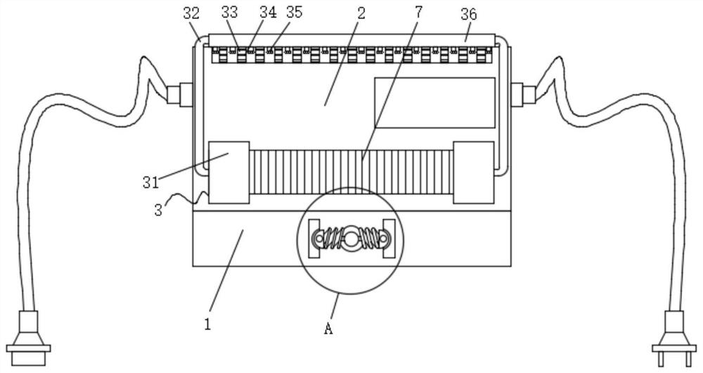
[0028] Such as Figure 1-3 As shown, the present invention provides an automatic power-off battery car charger, comprising: a self-power-off charger 2, the front of the self-power-off charger 2 is provided with an air vent 7, and the front of the self-power-off charger 2 is fixedly connected There is a heat dissipation mechanism 3, a storage case 1 is fixedly connected to the lower surface of the self-power-off charger 2, through holes 8 are opened on the left and right sides of the inner wall of the storage case 1, and a wire take-up mechanism 5 is arranged in the storage case 1, so that The outer surface of the take-up mechanism 5 is fixedly connected to the limit mechanism 4, and the heat dissipation mechanism 3 includes a mounting cover 31; wherein, the back side of the mounting cover 31 is fixedly connected to the front of the self-power-off charger 2, and the number of the mounting covers 31 is Two, the installation cover 31 is located on the front of the air vent 7 , an...
Embodiment 2
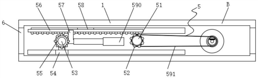
[0034] Such as Figure 1-4 As shown, this embodiment provides an automatic power-off battery car charger. The difference from Embodiment 1 is that the take-up mechanism 5 includes a first rotating shaft 51, and the first rotating shaft 51 is sleeved on the front of the storage case 1 and snapped into place. In the first bearing, the outer surface of the first rotating shaft 51 is clamped with the first gear 52, the upper surface of the first gear 52 is meshed with the rack 56, and the back of the rack 56 is fixedly connected with the second slider 58, the second The sliding block 58 is slidably connected in the second chute provided on the back side of the inner wall of the storage case 1 , and the front side of the rack 56 is fixedly connected with a telescopic rod 590 through the connecting rod 57 .
[0035] Preferably, in one of the preferred technical solutions of this embodiment, the telescopic rod 590 is fixedly connected to the back of the inner wall of the storage case...
Embodiment 3
[0041] Such as Figure 1-4 As shown, this embodiment provides an automatic power-off battery car charger. The difference from Embodiment 2 is that the limit mechanism 4 includes a spring 43, and the front of the storage case 1 is fixedly connected with two fixing plates 41 The opposite surfaces of the two fixing plates 41 are provided with limit slots, the left and right sides of the first rotating shaft 51 are fixedly connected with springs 43, the other end of the spring 43 is fixedly connected with the limit block 42, and the limit block 42 is inserted into the limit in the bit slot.
[0042] In practical applications, the limiting block 42 is inserted into the limiting slot by utilizing the elastic force of the spring 43 to avoid rotation of the first rotating shaft 51 .
[0043] Working principle: use the magnet 594 to make one end of the plug adsorb on the take-up column 59, and then use the rotation of the first rotating shaft 51 to make the second transmission wheel r...
PUM
 Abstract
Description
Claims
Application Information
 - R&D
- Intellectual Property
- Life Sciences
- Materials
- Tech Scout
- Unparalleled Data Quality
- Higher Quality Content
- 60% Fewer Hallucinations
Browse by: Latest US Patents, China's latest patents, Technical Efficacy Thesaurus, Application Domain, Technology Topic, Popular Technical Reports.
© 2025 PatSnap. All rights reserved.Legal|Privacy policy|Modern Slavery Act Transparency Statement|Sitemap|About US| Contact US: help@patsnap.com