
Electromagnetic ultrasonic transverse wave thickness measuring probe

An electromagnetic ultrasonic and transverse wave technology, applied in the direction of using ultrasonic/sonic/infrasonic waves, measuring devices, instruments, etc., can solve the problem of reducing the accuracy of thickness measurement, and achieve the effect of improving the accuracy of thickness measurement

Active Publication Date: 2021-01-29
PETROCHINA CO LTD +1
View PDF15 Cites 0 Cited by
  • Summary
  • Abstract
  • Description
  • Claims
  • Application Information

AI Technical Summary

Problems solved by technology

The shear wave direct incident electromagnetic ultrasonic sensor can measure the thickness under small lift-off, but when the lift-off increases, the fixed coil will no longer be in the strongest magnetic field region due to the change of the horizontal distribution of the magnetic field intensity, resulting in Decreased thickness measurement accuracy

Method used


Image

  • Electromagnetic ultrasonic transverse wave thickness measuring probe
  • Electromagnetic ultrasonic transverse wave thickness measuring probe
  • Electromagnetic ultrasonic transverse wave thickness measuring probe

Examples


Embodiment Construction

[0019] In order to make the purpose, technical solutions, and advantages of the embodiments of the present application clearer, the embodiments of the present application will be further described in detail below in conjunction with the accompanying drawings. Here, the exemplary embodiments of the application and their descriptions are used to explain the application, but not to limit the application.

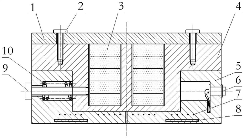
[0020] First of all, it needs to be explained that in this application, the bottom surface of the coil bobbin 5 is the contact surface between the electromagnetic ultrasonic shear wave thickness measuring probe and the member under test, the upper and lower positions are relative to the contact surface, and the direction away from the contact surface is "upper". ”, and the direction close to the contact surface is “down”.

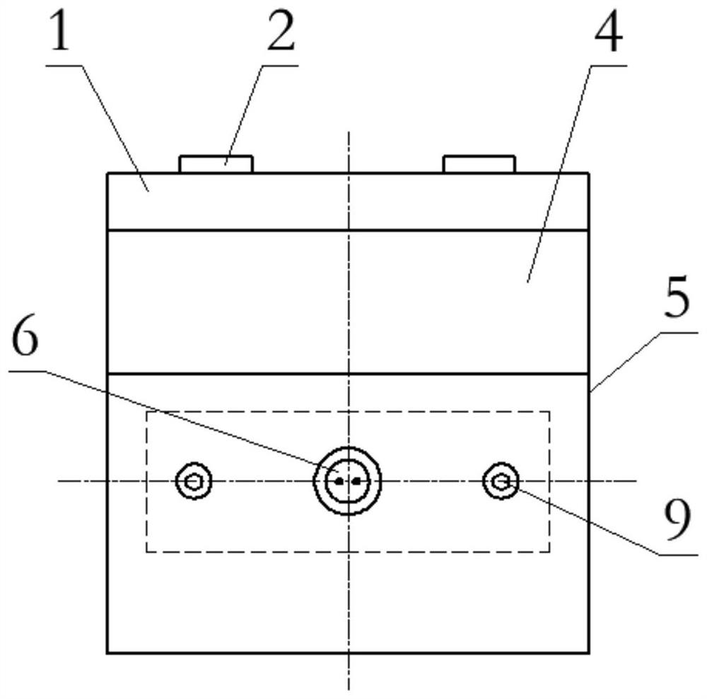
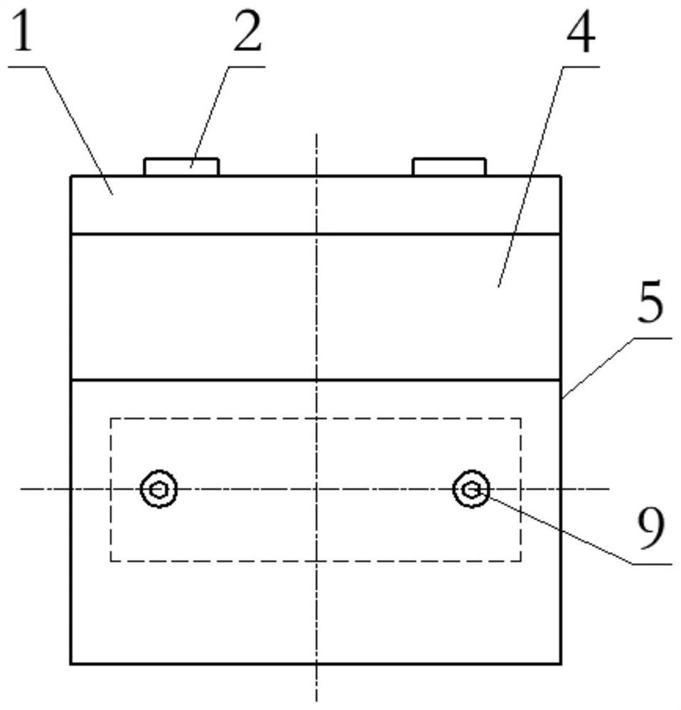
[0021] The embodiment of the present application provides an electromagnetic ultrasonic shear wave thickness measuring probe, such as figure 1 As shown, it...


PUM


Abstract

The invention discloses an electromagnetic ultrasonic transverse wave thickness measuring probe. The probe comprises a shell unit; two magnets set inside the shell unit; an excitation receiving unit which comprises two L-shaped coil frameworks arranged on the two outer sides of the shell unit, two coils fixed to the bottom faces of the L-shaped coil frameworks and correspond to the positions of the magnets respectively, springs which are arranged at the positions, making contact with the shell unit, of the side faces of the L-shaped coil frameworks, and adjusting bolts which are used for fixing the L-shaped coil frameworks and the side surfaces of the shell unit and can adjust the length screwed into the shell unit; the springs are used for pressing the heads of the adjusting bolts and theL-shaped coil frameworks; one end of each of the two coils is connected with an electromagnetic ultrasonic instrument at the same time, and the two coils are used for receiving excitation signals input by the electromagnetic ultrasonic instrument and feeding back echo signals to the electromagnetic ultrasonic instrument so that the electromagnetic ultrasonic instrument can determine the thicknessof a measured component according to the echo signals. The thickness measuring precision can be improved.

Description

technical field [0001] The present application relates to the technical field of ultrasonic nondestructive testing, in particular to an electromagnetic ultrasonic shear wave thickness measuring probe. Background technique [0002] This section is intended to provide a background or context to embodiments of the invention that are recited in the claims. The descriptions herein are not admitted to be prior art by inclusion in this section. [0003] Electromagnetic ultrasound is a new technology applied in the field of non-destructive testing. It excites ultrasonic waves in metal components through electromagnetic coupling and receives echo signals to explore the internal conditions of metal components, which can well reflect the thickness information of metal components. Compared with the traditional ultrasonic testing technology, electromagnetic ultrasound has the advantages of high precision and no need for couplant, so it is widely used in industrial production. For examp...

Claims


Application Information

Patent Timeline
Patent Type & Authority Applications(China)
IPC IPC(8): G01B17/02
CPCG01B17/02
Inventor 刘文才姜超彭其勇刘有为赵永涛武新军丁芳芳孙秉才张雪李佳宜
Owner PETROCHINA CO LTD
Learn More