Ditch cleaning device for agricultural planting

A technology for cleaning equipment and ditches, which is applied in grain processing, earth movers/excavators, construction, etc. It can solve the problems of inability to handle impurities, large volume of impurities, and impact on equipment cleaning efficiency, so as to prevent interference and improve crushing efficiency Effect

Inactive Publication Date: 2021-01-26
李克兰
View PDF1 Cites 2 Cited by
  • Summary
  • Abstract
  • Description
  • Claims
  • Application Information

AI Technical Summary

Problems solved by technology

A kind of ditch cleaning equipment for water conservancy projects in the above-mentioned patent has the following disadvantages: when the existing equipment treats the ditch, due to the large volume of impurities, the existing equipment cannot effectively treat impurities. Therefore, the cleaning efficiency of the equipment is affected

Method used


Image

  • Ditch cleaning device for agricultural planting
  • Ditch cleaning device for agricultural planting
  • Ditch cleaning device for agricultural planting

Examples


Embodiment 1

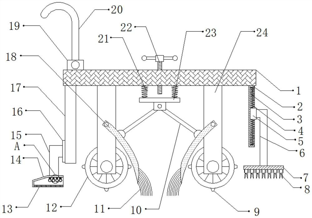
[0030] refer to Figure 1-3 , a kind of ditch cleaning equipment for agricultural planting, comprising a fixed seat 1, one side of the outer wall of the bottom of the fixed seat 1 is connected with a fixed plate 2 by bolts, and the outer wall of one side of the fixed plate 2 is provided with a fixed groove, and the opposite sides of the fixed groove A guide rod 3 is connected between the inner walls by bolts, and the outer wall of the guide rod 3 is slidably connected with a slider 5, and the outer wall of the guide rod 3 is sleeved with two first springs 4, and the two first springs 4 are located on the slider. 5, the outer wall of one side of the slider 5 is connected with a fixed rod 6 through bolts, and the bottom outer wall of the fixed rod 6 is connected with a support plate 7 through bolts, and the bottom outer wall of the support plate 7 is connected with a plurality of crushing teeth 8 through bolts. , and the shape of the crushing tooth 8 is similar to that of scisso...

Embodiment 2

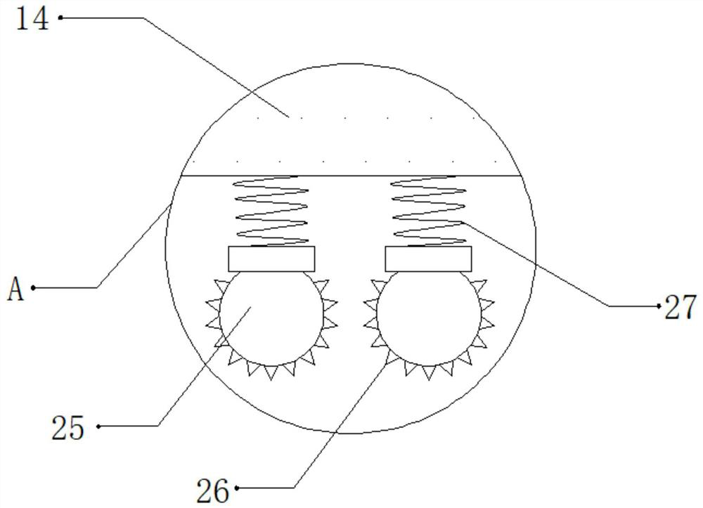
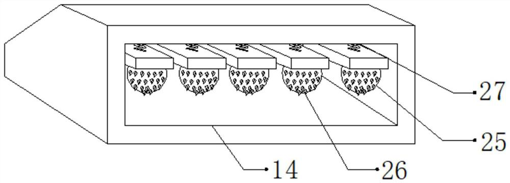
[0041] refer to Figure 4 , a kind of ditch cleaning equipment for agricultural planting. Compared with Embodiment 1, the outer wall of the bottom of the fixed plate 2 and the outer wall of the top of the support plate 7 are all connected with an impact block 28 by bolts, and the shape of the impact block 28 is T Type, corresponding to the position between the two impact blocks 28.

[0042] Working principle: When in use, when the ditch needs to be cleaned, push the push rod 20, move the device to both sides of the ditch through the moving wheel 12, move the device on the top of the ditch through the push rod 20, and make the device move through the bump 9 The equipment can vibrate when it is moving, so that the impurities and debris inside the ditch can be processed through vibration, which reflects the environmental protection of the equipment. Due to the rough road surface, when the equipment is moving, it will vibrate, so that through the first spring 4 Drive the crushing...


PUM


Abstract

The invention discloses a ditch cleaning device for agricultural planting. The ditch cleaning device comprises a fixed seat, wherein one side of the outer wall of the bottom of the fixed seat is fixedly connected with a fixed plate; a fixed groove is formed in the outer wall of one side of the fixed plate; a guide rod is fixedly connected between inner walls of two opposite sides of the fixed groove; the outer wall of the guide rod is in sliding connection with a sliding block; two first springs sleeve the outer wall of the guide rod; the two first springs are located at two sides of the sliding block; the outer wall of one side of the sliding block is fixedly connected with a fixed rod; the outer wall of the bottom of the fixed rod is fixedly connected with a supporting plate; and the outer wall of the bottom of the supporting plate is fixedly connected with a plurality of crushing teeth. The ditch cleaning device disclosed by the invention can be used for carrying out impacting and crushing treatment on impurities with relatively large sizes and the crushing efficiency of the equipment can be improved; the impurities can be prevented from being stuck at the bottom of a ditch andare not easy to shovel; and impurities and fragments in the ditch can be treated through vibration and the fragments can be prevented from being stuck on the surfaces of the crushing teeth to cause interferences on the crushing of the impurities.

Description

technical field [0001] The invention relates to the technical field of agricultural planting, in particular to a ditch cleaning device for agricultural planting. Background technique [0002] During agricultural planting, the function of the ditch is to guide the water flow, so as to irrigate the plants, and the larger impurities may fall into the ditch, which will block the ditch. Therefore, it is necessary to use cleaning equipment to The interior of the ditch is cleaned. [0003] After searching, the Chinese patent authorization number is CN209397702U, which discloses a kind of ditch cleaning equipment for water conservancy engineering, including a device main body, walking wheels and push plates. The walking wheels are arranged at the bottom four corners of the device main body. There are push plates on both sides, and the ends of the push plates are fixedly connected to the bottom of the front end of the main body of the device through the connecting rod. When the ditc...

Claims


Application Information

Patent Timeline
Patent Type & Authority Applications(China)
IPC IPC(8): E02F5/28B02C1/12B02C23/00
CPCB02C1/12B02C23/00B02C2201/06E02F5/282
Inventor 李克兰
Owner 李克兰
Why Eureka
Try Eureka