
Quantitative generation-reaction device and synchronous detection method for ammonia gas

A reaction device and ammonia gas generation technology, applied in the field of experimental instruments, can solve the problems of pollution detection, experimental result error, leakage, etc., and achieve the effect of avoiding pollution and leakage, and accurately calibrating real-time detection.

Pending Publication Date: 2021-01-26
NANJING UNIV OF INFORMATION SCI & TECH
View PDF6 Cites 0 Cited by
  • Summary
  • Abstract
  • Description
  • Claims
  • Application Information

AI Technical Summary

Problems solved by technology

Under the current research, the ammonia reaction environment used in the simulation experiments is mostly realized by purchasing commercial gas cylinders with a specific concentration of ammonia. However, the gas cylinders can only be used as ammonia generators rather than reaction devices. The process of the reaction site is prone to leakage, pollution and other problems and is not easy to be detected, resulting in large errors in the experimental results. At the same time, this method cannot flexibly adjust the concentration of ammonia gas required. Moreover, the ammonia gas cylinder is expensive and not portable. There are high requirements on the storage environment

Method used


Image

  • Quantitative generation-reaction device and synchronous detection method for ammonia gas
  • Quantitative generation-reaction device and synchronous detection method for ammonia gas
  • Quantitative generation-reaction device and synchronous detection method for ammonia gas

Examples


Embodiment 1

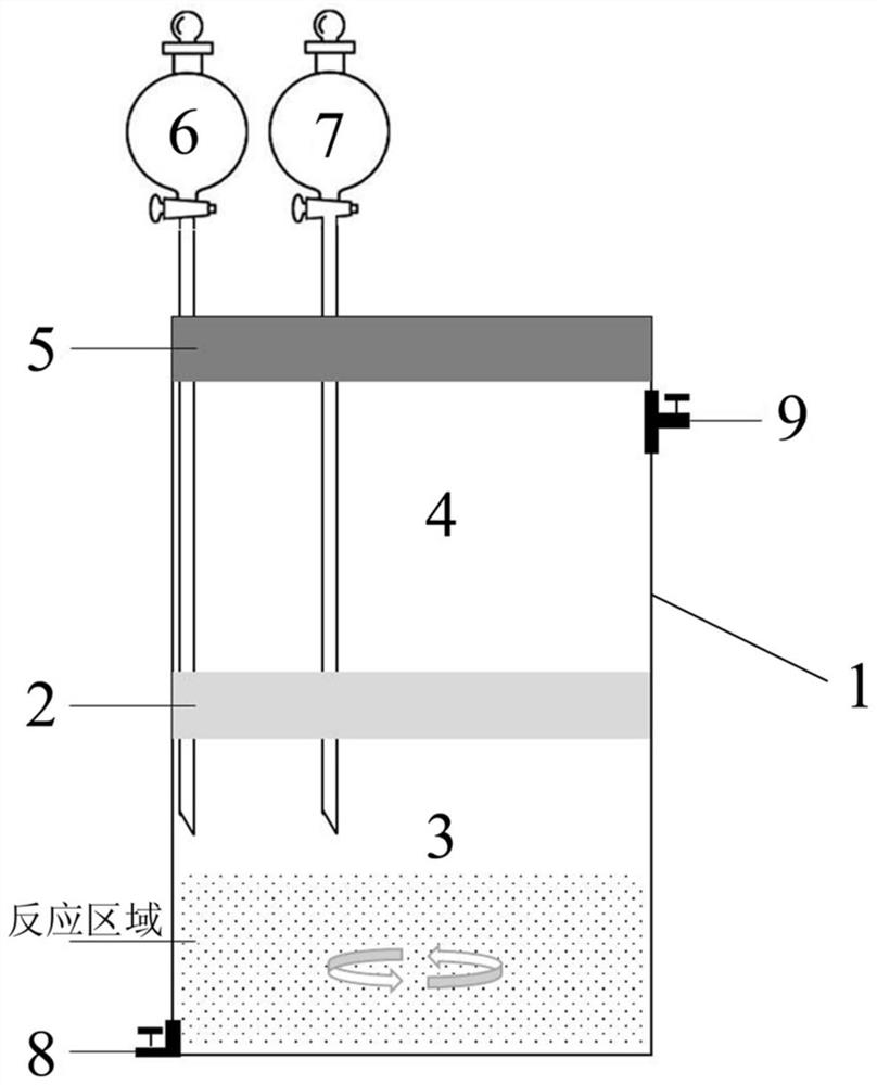
[0025] A quantitative ammonia gas generation-reaction device, such as figure 1 As shown, a first tank body 1 is included, and a desiccant spacer layer 2 (soda lime) is horizontally arranged in the first tank body 1, and an ammonia gas generating chamber 3 is below the desiccant spacer layer 2, so Above the desiccant spacer layer 2 is an ammonia gas reaction chamber 4; the top of the first tank body 1 is provided with a rubber cover 5 for keeping the container airtight, and the rubber cover 5 is provided with NH 4 Cl dosing funnel 6 and NaOH dosing funnel 7, the NH 4 The ends of the Cl dosing funnel 6 and the NaOH dosing funnel 7 are all arranged below the desiccant spacer layer 2; the bottom end of the side wall of the first tank body 1 is provided with a first valve 8 for the reaction liquid Sampling and discharge of reaction liquid, the top of the side wall of the first tank body 1 is provided with a second valve 9, which is used for the discharge of air in the first tank b...

Embodiment 2

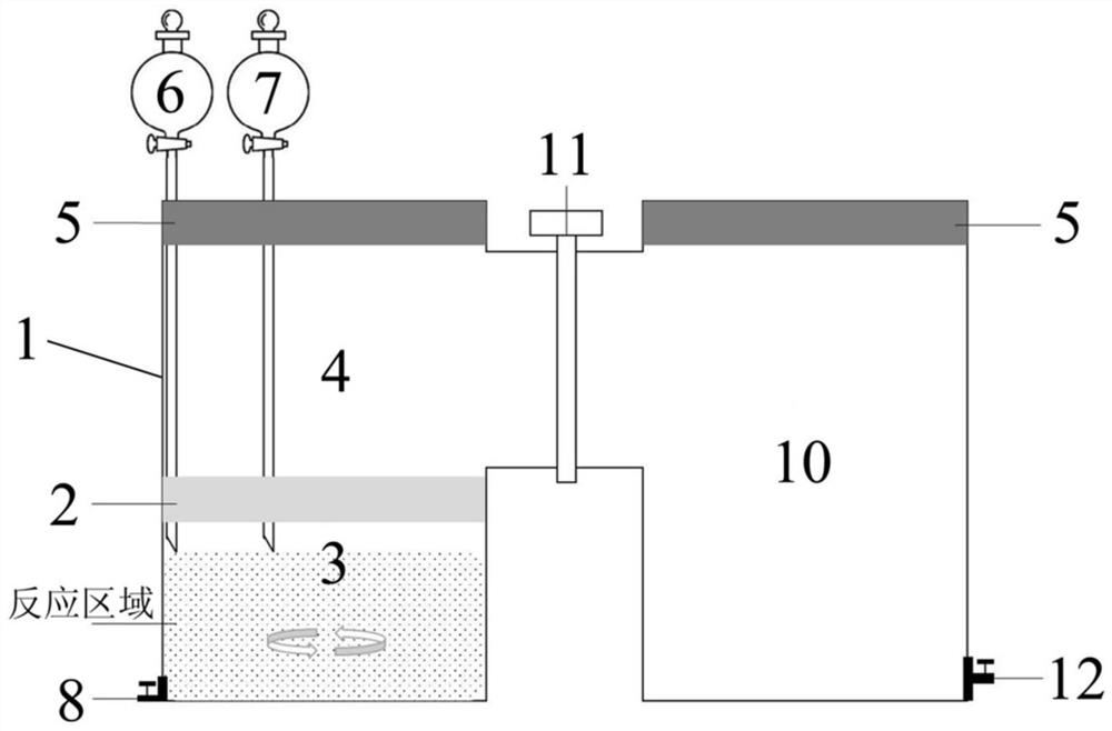
[0027] A quantitative ammonia gas generation-reaction device, such as figure 2 As shown, the split structure designed on the basis of Embodiment 1 (one-piece structure) also includes a second tank body 10, a third valve 11 and a fourth valve 12, wherein the second tank body 10 and the The first tank body 1 communicates with each other, and the communication is located at the side wall of the ammonia reaction chamber 4, and the communication is provided with a third valve 11, which is used to separate the ammonia generating device from the reaction device to form an independent A reaction place with quantitative ammonia concentration, the bottom end of the side wall of the second tank body 10 is provided with a fourth valve 12, which is used for the discharge of air in the second tank body 10 and the gas sampling of the generated ammonia gas, so The top of the second tank body 10 is also provided with a rubber cover 5 .

Embodiment 3

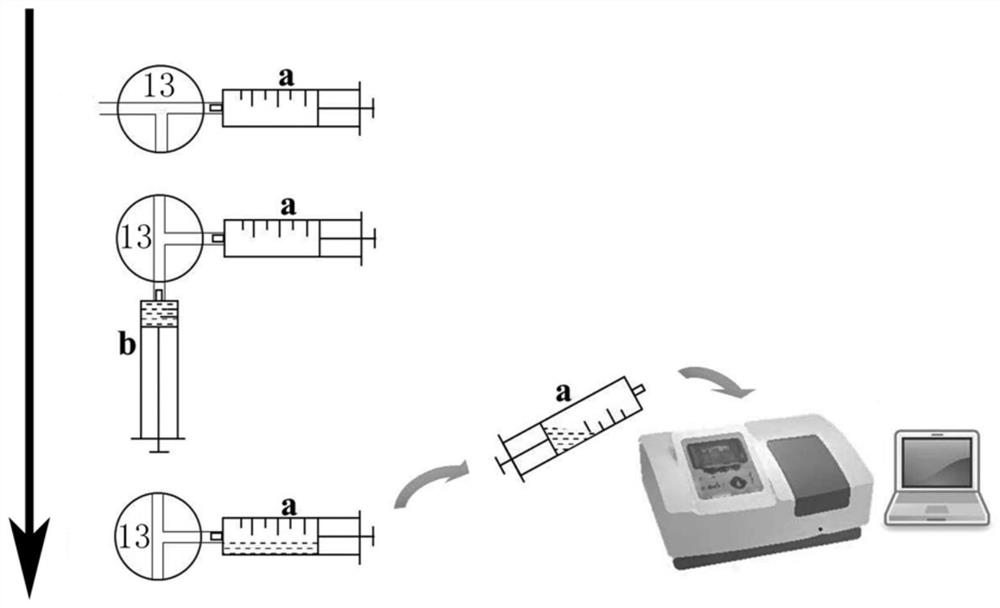
[0029] The ammonia gas synchronous detection method based on the ammonia gas quantitative generation-reaction device of embodiment 2, concrete steps are as follows:

[0030] (1) Quantitative generation of ammonia gas: firstly, the ammonium chloride solution is mixed with NH 4 Add the Cl dosing funnel 6 into the ammonia gas generating chamber 3 below the desiccant spacer layer 2, then slowly add sodium hydroxide from the NaOH dosing funnel 7 into the ammonium chloride solution in the ammonia gas generating chamber 3, and start Stir at a constant speed, and the following reaction occurs:

[0031] NH 4 Cl+NaOH=NaCl+NH 3 ↑+H 2 O,

[0032] Until the pH of the solution is more than or equal to 12, it is considered that all ammonium ions in the solution are all converted into ammonia, and the addition of sodium hydroxide is stopped, and the reaction is completed; use wet phenolphthalein test paper to carry out ammonia gas at the second valve 9 or the fourth valve 12. The generat...


PUM


Abstract

The invention discloses a quantitative generation-reaction device and a synchronous detection method for ammonia gas. The device comprises a first tank body, wherein a drying agent spacing layer is horizontally arranged at the inner lower part of the first tank body, an ammonia gas generation chamber is arranged below the drying agent spacing layer, and an ammonia gas reaction chamber is arrangedabove the drying agent spacing layer; a rubber cover is arranged at the top of the first tank body, two funnels are arranged on the rubber cover, and the ends of the two funnels are arranged below thedrying agent spacing layer; and a first valve is arranged at the bottom end of the side wall of the first tank body, a second valve is arranged at the top end of the side wall of the first tank body,and the second valve is located below the rubber cover. The device is combined with the self-developed closed sulfuric acid absorption synchronous detection method, so quantitative generation-reaction and synchronous detection of any ammonia gas concentration can be realized. The device is simple and easy to operate, and has important significance in production practice and scientific research experiments for researching generation, influence, synchronous detection and the like of ammonia gas with an accurate concentration.

Description

technical field [0001] The invention belongs to the technical field of experimental instruments, and in particular relates to an ammonia gas quantitative generation-reaction device and an ammonia gas synchronous detection method. Background technique [0002] Ammonia is an alkaline gas closely related to industrial and agricultural production activities, and the environmental problems caused by its excessive discharge have also aroused people's increasing attention and attention. Well-known water eutrophication, soil acidification, low utilization rate of agricultural fertilization, atmospheric smog and other hot environmental issues involving water, soil, air, food, etc. are all related to the direct discharge of ammonia or its secondary emissions in the environment. The reaction is closely related. Therefore, the research on the traceability, detection, monitoring and control technology of ammonia gas is becoming a hot and difficult point in the field of environmental pro...

Claims


Application Information

Patent Timeline
Patent Type & Authority Applications(China)
IPC IPC(8): C01C1/02G01N21/78
CPCC01C1/02G01N21/783
Inventor 李天玲周铭王婷婷黄家宇赵俊茹
Owner NANJING UNIV OF INFORMATION SCI & TECH
Learn More