
Engineering machinery supporting leg

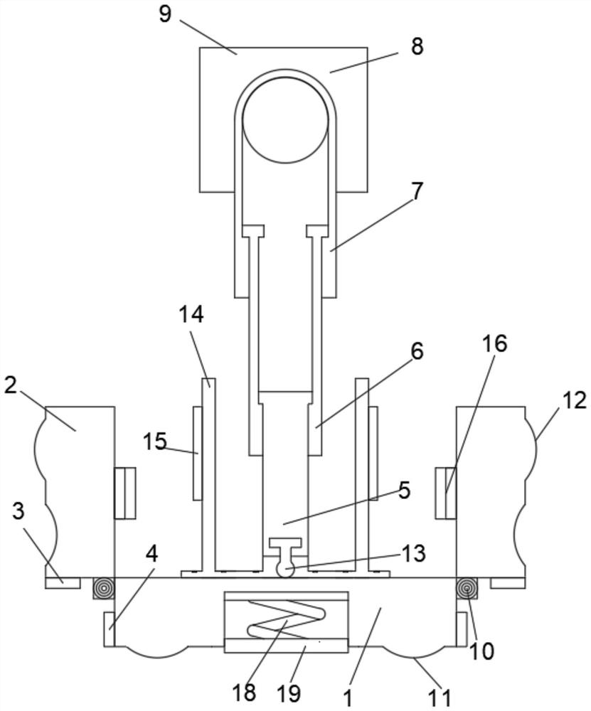
A technology of construction machinery and hydraulic rods, applied in cranes, vehicle maintenance, lifting vehicle accessories, etc., can solve the problems of improper engineering operation, delayed construction period, inability to fit the outriggers of construction machinery to the ground, etc., to prevent tilting. The effect of overturning accidents and improving safety performance

Pending Publication Date: 2021-01-26
SICHUAN UNIV
View PDF0 Cites 0 Cited by
  • Summary
  • Abstract
  • Description
  • Claims
  • Application Information

AI Technical Summary

Problems solved by technology

[0003] The current construction machinery outriggers cannot work on the ground for other reasons such as uneven roadbed or soft roadbed, which leads to other operations being unable to continue to work, so that some construction tasks that need to be completed on time cannot be completed, and the construction period is delayed. Secondly, some projects The height of the mechanical outriggers is fixed, and the outriggers of the construction machinery cannot be completely attached to the ground, which may cause improper operation during the construction, make the center shift, and easily cause overturning accidents

Method used


Image

  • Engineering machinery supporting leg
  • Engineering machinery supporting leg
  • Engineering machinery supporting leg

Examples


Embodiment Construction

[0018] The following will clearly and completely describe the technical solutions in the embodiments of the present invention with reference to the accompanying drawings in the embodiments of the present invention. Obviously, the described embodiments are only some, not all, embodiments of the present invention.

[0019] Examples of the described embodiments are shown in the drawings, wherein like or similar reference numerals designate like or similar elements or elements having the same or similar functions throughout. The embodiments described below by referring to the figures are exemplary and are intended to explain the present invention and should not be construed as limiting the present invention.

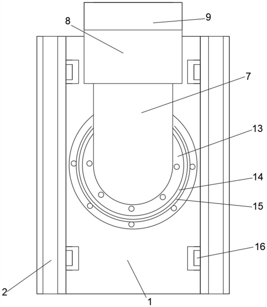
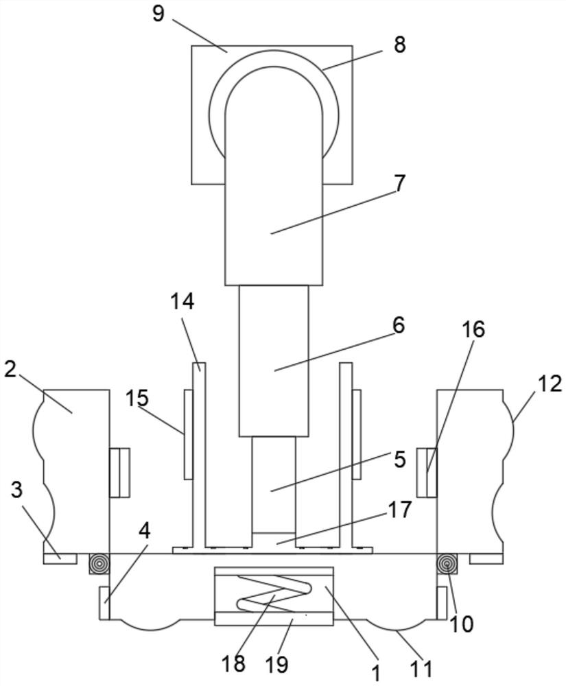
[0020] see Figure 1-3 , the present invention provides a technical solution: a construction machinery outrigger, comprising a main anti-compression base 1, an auxiliary anti-compression base 2 and a main hydraulic rod 7, the auxiliary anti-compression base 2 is located on b...


PUM


Abstract

The invention discloses an engineering machinery supporting leg, and relates to the technical field of engineering machinery. The engineering machinery supporting leg comprises a main compression-resistant base, auxiliary compression-resistant bases and main hydraulic rods; the auxiliary compression-resistant bases are located on the two sides of the outer wall of the main compression-resistant base; the main hydraulic rods are located at the bottom of the main compression-resistant base; a fixed connecting block is fixedly arranged in the center of the top of the main compression-resistant base; and a protection pipe is fixedly arranged at the top, close to the fixed connecting block, of the main compression-resistant base; and the center of the outer wall of the protection pipe is provided with a protection sleeve in a sleeved mode. Through the main pressure-resistant base, the auxiliary pressure-resistant bases, a main buffer block, an auxiliary buffer block, a main stabilizing block and an auxiliary stabilizing block, engineering machinery can operate on the ground with an uneven roadbed, the working efficiency is improved, the construction period time is shortened, and throughthe main hydraulic rods, an auxiliary hydraulic rod, the protection sleeve, the fixed connecting block and a rotary connecting column, when the engineering machinery operates, the engineering machinery is supported on the supporting leg, so that tipping accidents are prevented, and the safety performance is improved.

Description

technical field [0001] The invention relates to the technical field of engineering machinery, in particular to an engineering machinery outrigger. Background technique [0002] At present, construction machinery includes truck cranes, concrete pump trucks, etc. When the construction machinery arrives at the job site, the outrigger arms are expanded by swinging or telescopically extending the supporting legs to the ground to support the car body. Due to reasons such as subsidence or soft roadbed, outrigger construction machinery often overturns during operation. [0003] The current construction machinery outriggers cannot work on the ground for other reasons such as uneven roadbed or soft roadbed, which leads to other operations being unable to continue to work, so that some construction tasks that need to be completed on time cannot be completed, and the construction period is delayed. Secondly, some projects The height of the mechanical outriggers is fixed, and it is impo...

Claims


Application Information

Patent Timeline
IPC IPC(8): B66C23/80B66C23/88B60S9/10
CPCB66C23/80B66C23/88B60S9/10B66C2700/03
Inventor 王俊凯赵武陈领伍博刘也琪宋依繁
Owner SICHUAN UNIV
Learn More