Thin-wall rubber ring injection molding mold opening automatic shearing equipment
A technology of shearing equipment and rubber ring, applied in the field of automatic shearing equipment for thin-walled rubber ring injection molding, can solve the problems of thin-walled rubber ring deformation, etc., to avoid uneven force, ensure stability, and avoid deformation. Effect
- Summary
- Abstract
- Description
- Claims
- Application Information
AI Technical Summary
Problems solved by technology
Method used
Image
Examples
Embodiment 1
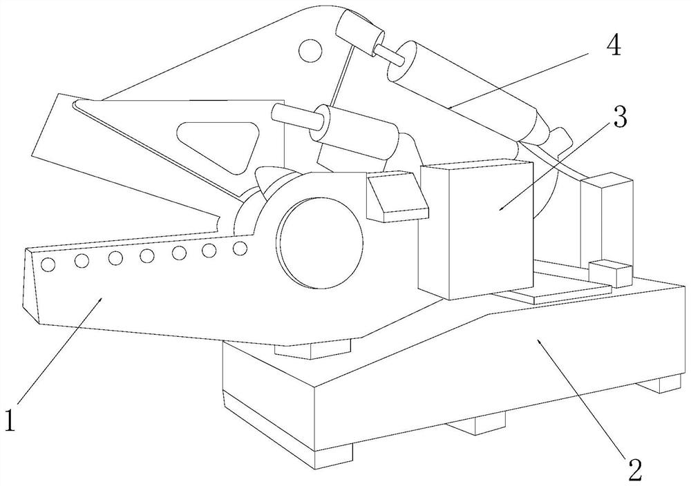
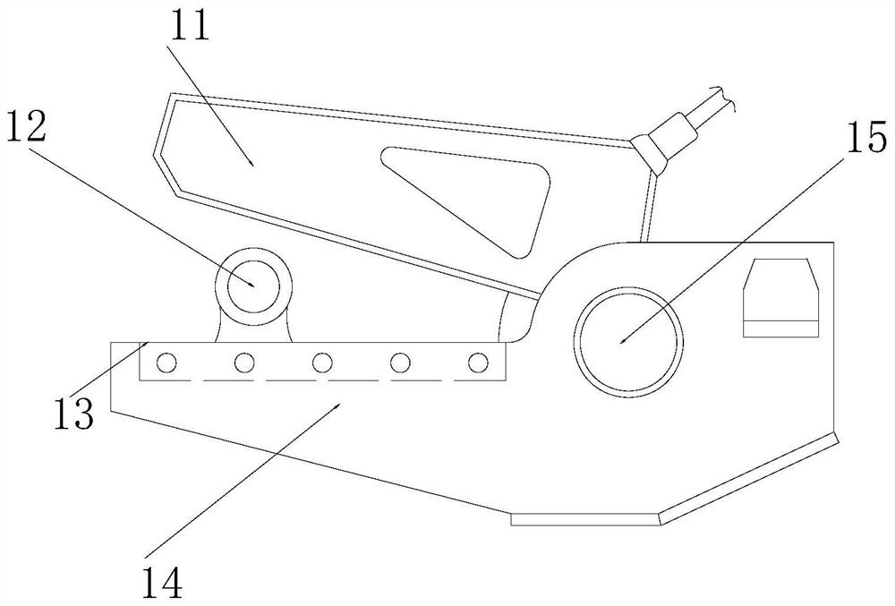
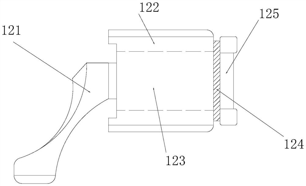
[0025] as attached figure 1 to attach Figure 5 Shown:
[0026] The invention provides an automatic shearing equipment for injection molding of thin-walled rubber rings. Its structure includes a cutting mechanism 1, a mounting seat 2, a control box 3, and a hydraulic rod 4. Above, the mounting seat 2 is embedded and installed directly below the control box 3, and the control box 3 is embedded and installed directly below the hydraulic rod 4, and the hydraulic rod 4 is bolted directly above the cutting mechanism 1, so The cutting mechanism 1 includes a cutting blade 11, a mounting seat 12, an inlay groove 13, a shear plate 14, and an inlay shaft 15. The cutting blade 11 is inlaid directly above the mounting seat 12, and the mounting seat 12 is installed on the mounting seat 12 by welding. The outer surface of the upper end of the inlay groove 13, the inlay groove 13 is inlaid on the upper end surface of the shear plate 14, the inner end surface on the right side of the shear ...
Embodiment 2
[0033] as attached Figure 6 to attach Figure 7As shown: the support mechanism 125 includes a balance plate 51, an inlay ring 52, and a mounting block 53. The balance plate 51 is evenly inlaid and mounted on the inner end surface of the inlaid ring 52, and the inner end surface of the inlaid ring 52 is inlaid and installed. The installation block 53 is connected to the balance plate 51 by welding, and the installation angle of the balance plate 51 is slightly tilted, and the outer ring of the thin-walled rubber ring is expanded to avoid cutting the end point through the slightly tilted angle. Slack appears.
[0034] Wherein, the balance plate 51 includes a rubber block 511, a support plate 512, a rotating shaft 513, a connecting rod 514, and a second spring 515. The right end surface of 512 is connected to the second spring 515 by inserting and engaging, the rotating shaft 513 is located on the right side of the lower end of the support plate 512, the connecting rod 514 is ...
PUM
 Abstract
Description
Claims
Application Information
 - R&D
- Intellectual Property
- Life Sciences
- Materials
- Tech Scout
- Unparalleled Data Quality
- Higher Quality Content
- 60% Fewer Hallucinations
Browse by: Latest US Patents, China's latest patents, Technical Efficacy Thesaurus, Application Domain, Technology Topic, Popular Technical Reports.
© 2025 PatSnap. All rights reserved.Legal|Privacy policy|Modern Slavery Act Transparency Statement|Sitemap|About US| Contact US: help@patsnap.com


