Device for collecting medical waste
A technology of medical waste and tanks, which is applied in the field of waste collection devices, can solve the problems of residual bacteria and viruses, incomplete disinfection of medical waste, and the impact of storage space occupied by medical waste, so as to facilitate disinfection, recycling, and reduce waste. The effect of storage space
- Summary
- Abstract
- Description
- Claims
- Application Information
AI Technical Summary
Problems solved by technology
Method used
Image

Examples
Embodiment 1
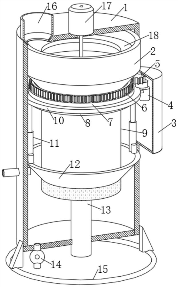
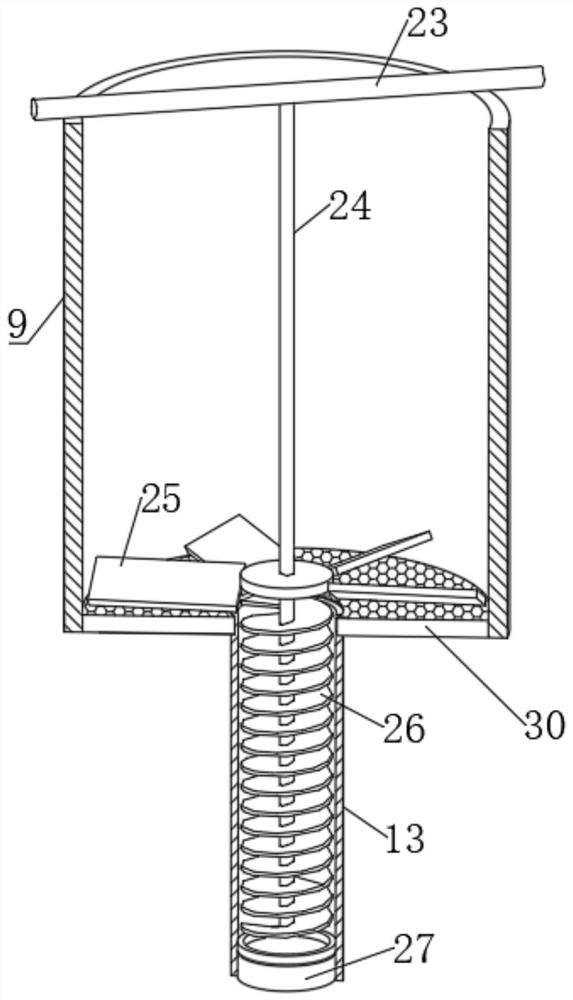
[0027] A device for collecting medical waste, comprising a tank body 1, a funnel 12 with a trumpet-shaped structure is fixedly connected to the tank body 1, a sleeve 9 is slidably sleeved in the funnel 12, and the outer edge of the lower end of the sleeve 9 is There are a plurality of evenly distributed drainage outlets throughout, the lower end of the casing 9 is internally fixed with a grid plate 30, and the center of the lower end of the tank body 1 is fixedly connected with a discharge pipe 13 through a round hole, and the discharge The inner edge of the lower end of the pipe 13 is connected with a sealing plate 27, and the center of the grid plate 30 is slidingly socketed with the pipe wall of the discharge pipe 13 through a round hole, and the upper end of the discharge pipe 13 extends into the casing 9. The outer edge of the upper end of the casing 9 is connected with a transmission mechanism, and the tank body 1 is fixedly connected with a crushing bucket 2 above the ca...
Embodiment 2
[0029] Embodiment 2: the difference based on Embodiment 1 is;
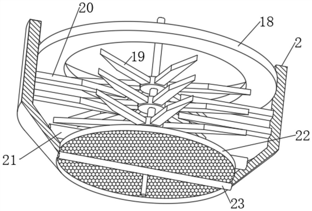
[0030] The crushing mechanism includes a rotating shaft vertically arranged in the crushing bucket 2. The upper end of the rotating shaft is rotationally connected with the center of the upper inner wall of the tank body 1 through a rolling bearing. A plurality of evenly distributed movable blades 19 are fixedly connected to the shaft wall of the rotating shaft. The inner wall of 2 is fixedly connected with a plurality of evenly distributed fixed blades 20, a plurality of movable blades 19 and a plurality of fixed blades 20 are arranged alternately, the lower end of the rotating shaft is connected with a fixed rod 21 through a sealed bearing, and the two ends of the fixed rod 21 are respectively connected to The inner walls on opposite sides of the crushing bucket 2 are fixedly connected, the lower opening of the crushing bucket 2 is fixedly connected with a mesh plate 22 and a cross bar 23, the cross bar 23 is loc...
Embodiment 3
[0032] Embodiment 3: the difference based on embodiment 1 is;
[0033] The transmission mechanism includes a first annular plate 7, a circular ring 10 and a second annular plate 8 which are sleeved on the tube wall of the casing 9, and the inner sides of the first annular plate 7 and the second annular plate 8 are connected with the tube wall of the sleeve 9. Fixed connection, the inner side of the ring 10 is slidingly socketed with the pipe wall of the casing 9, the side wall of the ring 10 is slidingly socketed with the inner wall of the tank body 1, and the lower end of the ring 10 is symmetrically fixedly connected with two electric push rods 11 The ends of the two electric push rods 11 away from the ring 10 are respectively fixedly connected to the upper end of the funnel 12, the upper end of the first annular plate 7 is fixedly connected to the ring gear 6, and the right end of the tank body 1 is provided with a rectangular opening, and inside the rectangular opening is a...
PUM
 Abstract
Description
Claims
Application Information
 - R&D
- Intellectual Property
- Life Sciences
- Materials
- Tech Scout
- Unparalleled Data Quality
- Higher Quality Content
- 60% Fewer Hallucinations
Browse by: Latest US Patents, China's latest patents, Technical Efficacy Thesaurus, Application Domain, Technology Topic, Popular Technical Reports.
© 2025 PatSnap. All rights reserved.Legal|Privacy policy|Modern Slavery Act Transparency Statement|Sitemap|About US| Contact US: help@patsnap.com