Novel abdominal cavity cathetering drainage assembly

An abdominal cavity and catheter placement technology, applied in catheters, suction devices, hypodermic injection devices, etc., can solve problems such as increased infection risk, high abdominal pressure, and difficulty in successful drainage, avoiding the risk of reverse infection, reducing the probability of blockage, and quickly and quickly. effect of connection

Pending Publication Date: 2021-01-26
周昱岐
View PDF0 Cites 0 Cited by
  • Summary
  • Abstract
  • Description
  • Claims
  • Application Information

AI Technical Summary

Problems solved by technology

However, in view of the characteristics of peritoneal effusion drainage, there are still many defects and inconveniences in actual use: ①The abdominal cavity is a body cavity that is much larger than blood vessels. The inlet of the drainage tube floats above the ascites, making it difficult to drain successfully; ②Ascites with exudate properties (inflammation, malignant tumor, etc.) is often turbid and viscous, containing a lot of flocs, and the drainage tube with only one inlet is often blocked ③In the case of a large amount of ascites, the tension of the abdominal wall is extremely high and the pressure of the abdominal cavity is extremely high. Exudate, aggravating the risk of local infection; ④The drainage tube is single-channel and dual-flow, and it is easy to contaminate and increase the risk of infection during intraperitoneal injection of drugs; Renovation", extremely inconvenient

Method used


Image

  • Novel abdominal cavity cathetering drainage assembly
  • Novel abdominal cavity cathetering drainage assembly
  • Novel abdominal cavity cathetering drainage assembly

Examples


Embodiment Construction

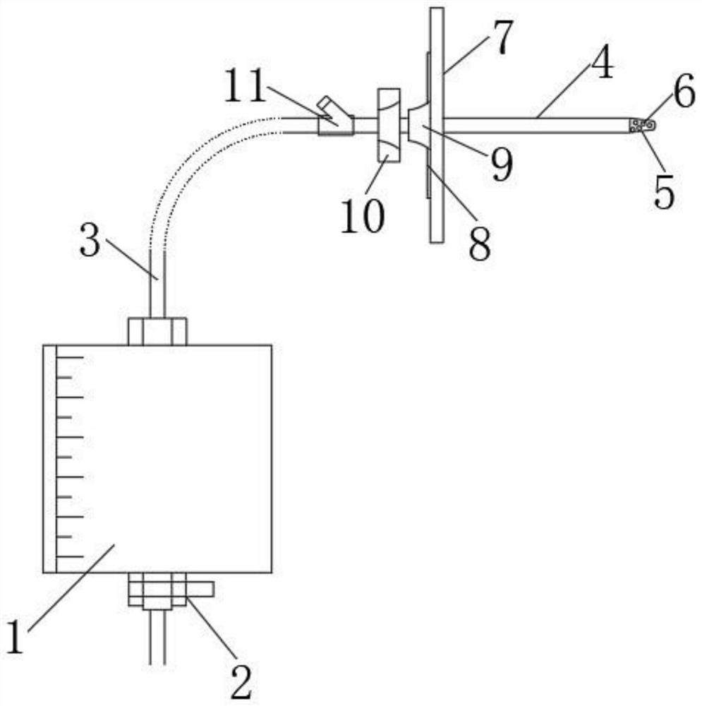
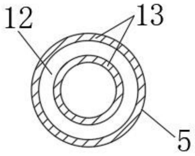
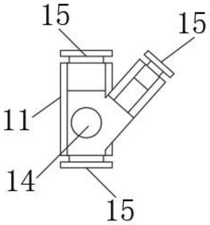
[0024] Such as Figure 1-6 It is a schematic diagram of the structure of the present invention, a new type of abdominal tube drainage assembly, including a drainage bag 1, a discharge port 2 is located below the drainage bag 1, a connecting tube 3 is connected to the drainage tube 4 through a three-way seat 11, and the end of the drainage tube 4 There is a drainage head 5, and a plurality of through holes 6 are arranged on the drainage head 5.

[0025] When this novel peritoneal catheter drainage assembly is in use, the drainage head 5 at the end of the drainage tube 4 is placed in the patient's abdominal cavity, and then the intraperitoneal effusion is introduced from the drainage tube 4 into the drainage bag 1, and finally There is discharge from the position of the discharge port 2, and the position of the oblique interface on the tee seat 11 can inject the drug, so as to prevent the dirt in the drainage bag 1 from going backward from the position of the drug injection port...


PUM


Abstract

The invention relates to the technical field of abdominal cavity drainage, in particular to a novel abdominal cavity cathetering drainage assembly. The novel abdominal cavity cathetering drainage assembly comprises a drainage bag, a discharging opening is formed in the lower portion of the drainage bag, a connecting pipe is connected with a drainage pipe through a three-way base, a drainage head is arranged at the tail end of the drainage pipe, and a plurality of through holes are formed in the drainage head. The novel abdominal cavity cathetering drainage assembly has the advantages that firstly, a nickel alloy is embedded into the inner layer of the drainage pipe, so that the drainage pipe can be prevented from being spirally bent; secondly, a plurality of through holes are formed in thepipe head of the drainage pipe, so that the blockage probability can be greatly reduced; thirdly, the attaching piece for fixing the drainage pipe on the abdominal wall is made of a gel material, sothat the drainage pipe is perfectly attached to the abdominal wall, and ascites exosmosis is avoided; fourthly, the drainage pipe is externally connected with a manual three-way valve capable of controlling the flow direction, a quick connector is adopted, forward drainage and reverse injection are completely separated, and the risk of reverse infection is avoided; and fifthly, the negative pressure drainage bag is provided with the quick connector and can be quickly and conveniently connected with the drainage pipe.

Description

technical field [0001] The invention relates to the technical field of abdominal cavity drainage, in particular to a novel abdominal cavity catheter drainage assembly. Background technique [0002] Paracentesis catheter drainage is a common clinical puncture operation, which is widely used to reduce ascites caused by various reasons (infectious peritonitis, liver cirrhosis, malignant tumor peritoneal metastasis, etc.). [0003] The specific method of abdominal puncture catheter drainage is as follows: select a suitable puncture point on the patient's abdominal wall, after routine disinfection and local anesthesia, insert a puncture needle with a core into the abdominal cavity, insert the guide wire into the needle core and insert it into the abdominal cavity, and exit the puncture The needle is inserted into the peritoneal drainage tube along the guide wire, the guide wire is withdrawn, the drainage tube is fixed on the abdominal wall, and the drainage tube is connected with...

Claims


Application Information

Patent Timeline
IPC IPC(8): A61M1/00A61M25/04
CPCA61M25/04A61M2210/1021A61M1/69A61M1/73A61M1/86A61M2210/005
Inventor 周昱岐江苏闽朱康平李相勇袁俊菲傅海涛
Owner 周昱岐
Why Eureka
Try Eureka