
Method for operating a regenerative heat reservoir arrangement and heat reservoir arrangement

A regenerator and regenerative technology, applied in regenerative heat exchangers, thermal storage equipment, indirect heat exchangers, etc., can solve the problems of low utilization rate and increase energy storage costs, and achieve the reduction of thermal storage costs, The effect of low compressor power consumption

Active Publication Date: 2021-01-22
CARBON CLEAN TECH GMBH
View PDF8 Cites 0 Cited by
  • Summary
  • Abstract
  • Description
  • Claims
  • Application Information

AI Technical Summary

Problems solved by technology

Low utilization with known methods of operating regenerative thermal storage systems increases the cost of energy storage since most thermal storage materials are not used to actively store thermal energy

Method used

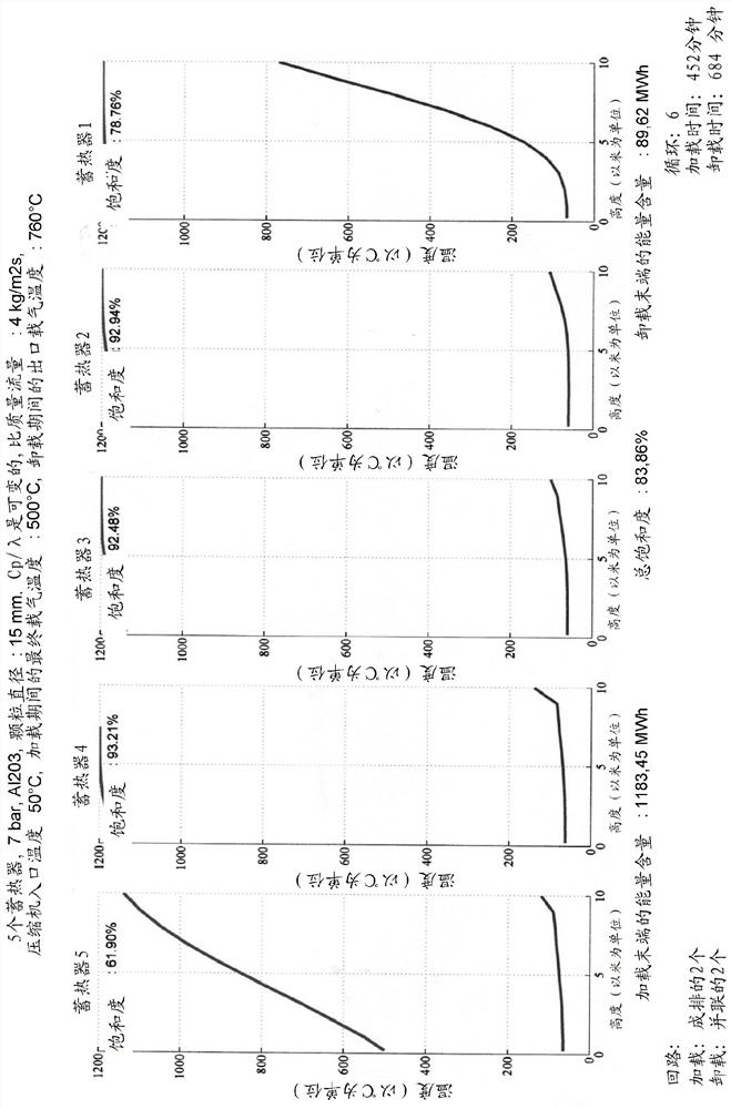
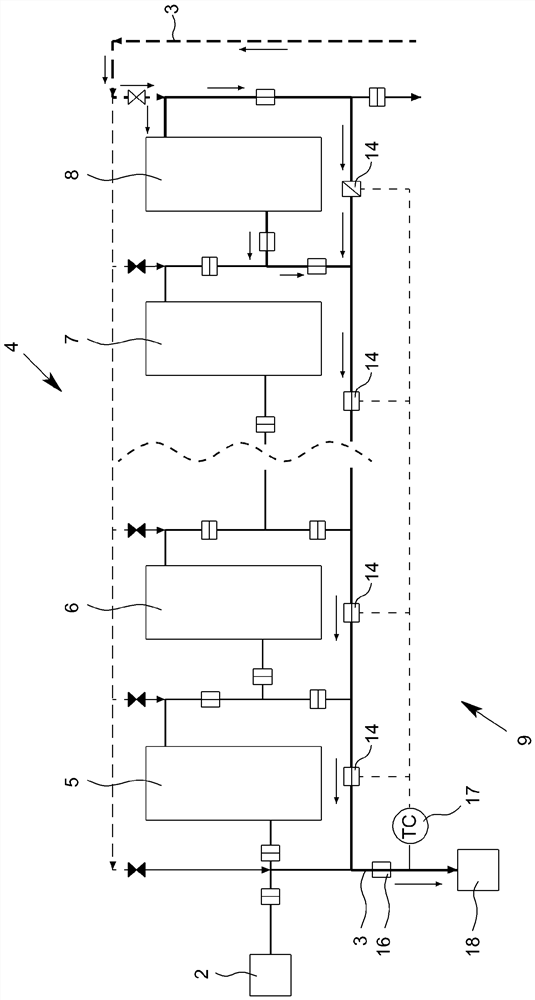
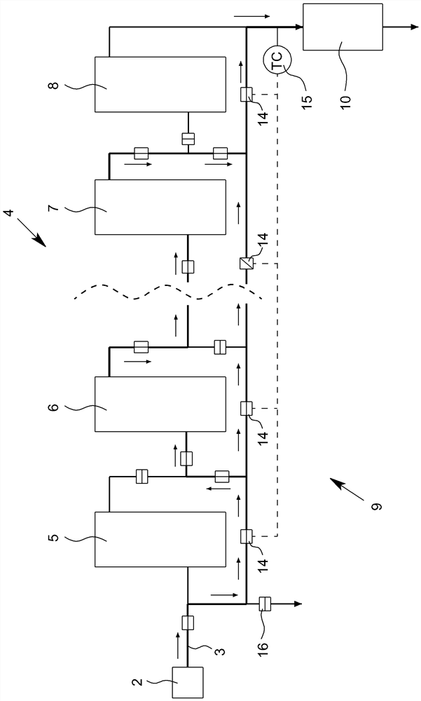

Image

  • Method for operating a regenerative heat reservoir arrangement and heat reservoir arrangement
  • Method for operating a regenerative heat reservoir arrangement and heat reservoir arrangement
  • Method for operating a regenerative heat reservoir arrangement and heat reservoir arrangement

Examples


Embodiment Construction

[0046] figure 1 Shown is a known heat accumulator arrangement 1 with at least one gas heater 2 for heating a carrier gas 3 , in particular air, and with a heat accumulator row 4 , for example with a series Four other heat accumulator modules 5 to 8 are connected. Of course, more or fewer than four heat accumulator modules 5 to 8 can also form a heat accumulator row 4 .

[0047] A blower or compressor 6 is also provided.

[0048] The heat accumulator arrangement 1 may correspond to the heat accumulator arrangement described in the publication DE 10 2014 017 346 A1 and is operated according to the procedure described in the aforementioned publication. The disclosure content of DE 10 2014 017 346 A1 is fully included in the disclosure content of the present description both with respect to the type and design of the heat storage device 1 and with regard to known operating procedures.

[0049] During the loading cycle or during the loading process of the regenerator modules 5 t...


PUM


Abstract

The invention relates to a method for operating a regenerative heat reservoir arrangement (9), wherein the heat reservoir arrangement (9) has: at least one gas heater (2) for heating a carrier gas (3), in particular for heating air; a heat reservoir row (4) with multiple heat reservoir modules (5); and at least one compressor (6), wherein, during a charging cycle, carrier gas (3) heated in the gasheater (2) flows through at least one heat reservoir module (5-8), preferably multiple subsequent heat reservoir modules (5-8) of the heat reservoir row (4), the at least one heat reservoir module isthermally charged by the transfer of heat from the heated carrier gas (3) to a heat storage material of the heat reservoir module (5-8) and the carrier gas (3) is cooled during the charging process,wherein if, after the charging of a heat reservoir module (5-7), the carrier gas temperature reaches or exceeds a minimum charging temperature for a subsequent heat reservoir module (6-8) in the heatreservoir row (4), the carrier gas (3) is fed to the subsequent heat reservoir module (6-8) for charging, and wherein the carrier gas (3) is recirculated if the carrier gas temperature falls below theminimum charging temperature for the subsequent heat reservoir module (6-8), and the carrier gas (3), when recirculated, is fed to the compressor (6) and, after compression, is fed back to the gas heater (2) for reheating of the carrier gas (3).

Description

technical field [0001] The invention relates to a method for operating a regenerative heat accumulator arrangement comprising at least one gas heater for heating a carrier gas, in particular for heating air, with a plurality of heat accumulator modules The regenerator bank and at least one compressor, wherein, during the loading cycle, at least one regenerator module in the regenerator row, preferably a plurality of subsequent regenerator modules, is heated by the carrier gas in the gas heater passes through, and is thermally loaded by heat transfer from the heated carrier gas to the heat storage material of the regenerator module, and during loading, the carrier gas is cooled, wherein, when the carrier gas after loading the regenerator module When the temperature reaches or exceeds the lowest loading temperature of the subsequent regenerator module in the regenerator row, the cooled carrier gas is supplied to the subsequent regenerator module for loading, and wherein, if the ...

Claims


Application Information

Patent Timeline
Patent Type & Authority Applications(China)
IPC IPC(8): F28D17/04F01K3/00F01K23/10F28D20/00
CPCF01K3/00F01K23/101F28D17/04F28F27/006F28D20/0056Y02E60/14F28D20/00F28D21/00F28D2021/0019
Inventor K·克诺普
Owner CARBON CLEAN TECH GMBH
Learn More