
Direct-current combiner box, inverter, photovoltaic system and protection method

A technology of DC confluence and combiner box, which is applied in the field of photovoltaic system and protection, inverter and DC combiner box, and can solve the problems of combiner box damage, cable burnt, etc.

Pending Publication Date: 2021-01-22
HUAWEI DIGITAL POWER TECH CO LTD
View PDF5 Cites 7 Cited by
  • Summary
  • Abstract
  • Description
  • Claims
  • Application Information

AI Technical Summary

Problems solved by technology

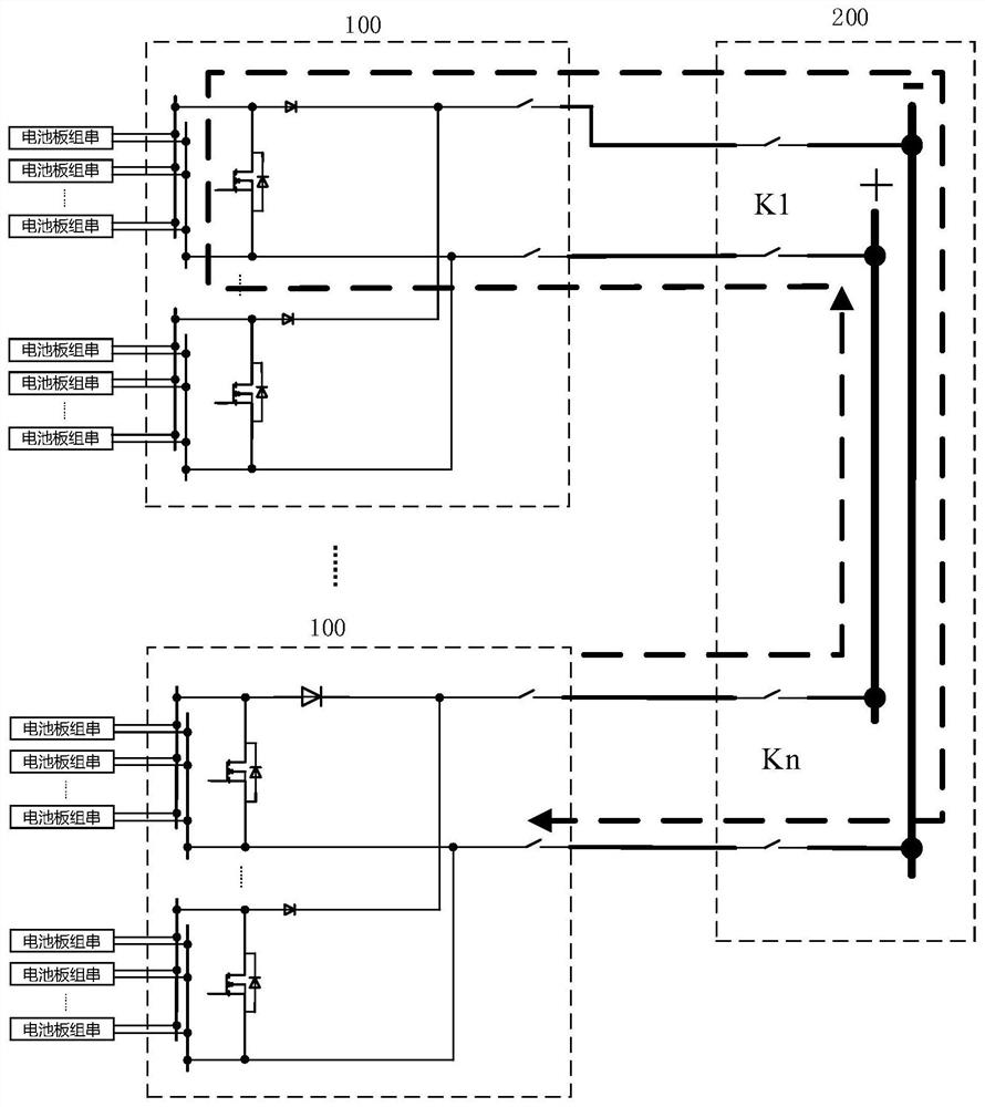
[0008] At this time, when the output switches (K1-Kn) of each combiner box are closed, the output voltage of the combiner box will be quickly pulled to zero, and the output current will be the sum of the short-circuit current of each input battery string, and all the current will sink into a short-circuited branch circuit or a combiner box where the positive and negative cables are connected incorrectly, causing overcurrent burning of the cable or damage to the combiner box

Method used


Image

  • Direct-current combiner box, inverter, photovoltaic system and protection method
  • Direct-current combiner box, inverter, photovoltaic system and protection method
  • Direct-current combiner box, inverter, photovoltaic system and protection method

Examples


Embodiment 1

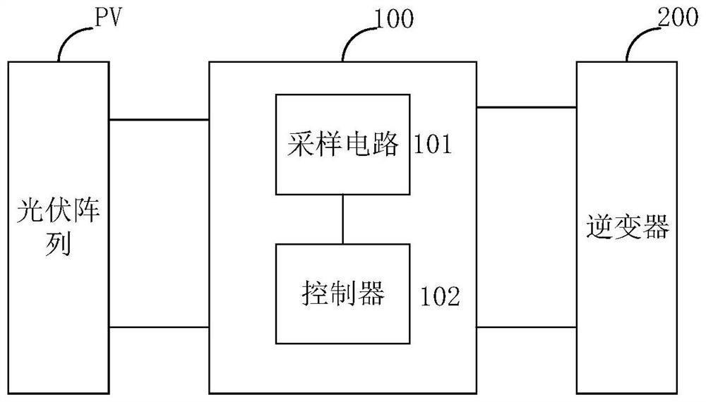
[0047]Seefigure 2 The figure is a schematic diagram of a DC combiner box provided by an embodiment of the application.

[0048]The output end of the DC combiner box 100 provided in this embodiment is connected to the input end of the inverter 200, that is, the combiner box on the DC side.

[0049]For the convenience of description, the DC combiner box will be referred to as the combiner box for short.

[0050]The input end of the combiner box 100 is used to connect the photovoltaic array PV.

[0051]In practice, the photovoltaic array PV can include multiple photovoltaic strings, and multiple photovoltaic strings can be connected in parallel. In order to provide power output capability, each photovoltaic string includes multiple photovoltaic panels connected in series.

[0052]The positive output terminal of the combiner box 100 is used to connect the positive input terminal of the inverter 200 through an output positive cable, and the negative output terminal of the combiner box 100 is used to co...

Embodiment 2

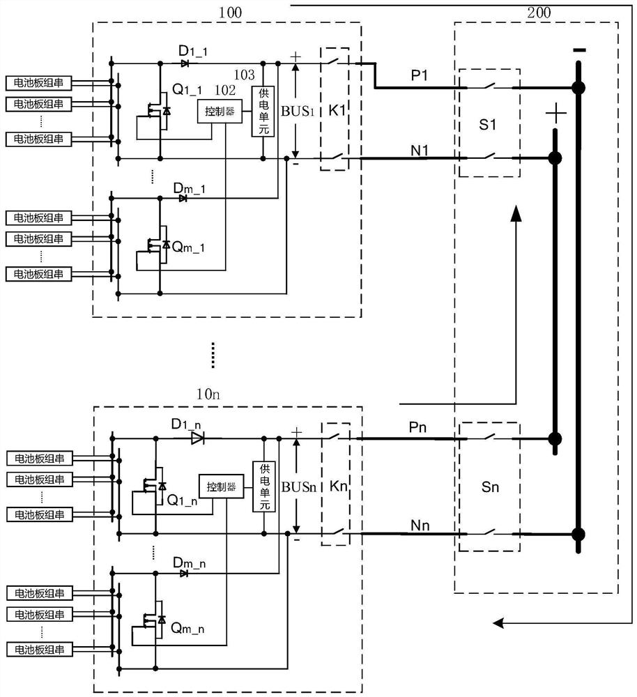
[0067]The following takes the DC / DC converter included in the combiner box as an example to introduce. The DC / DC converter is used to convert the direct current output from the photovoltaic array and output it to the inverter; specifically, the DC / DC converter is used as a boost converter The device Boost is introduced as an example.

[0068]The switching device in the combiner box includes at least the main power tube in the DC / DC converter;

[0069]When a short circuit or reverse connection occurs between the output positive cable and the output negative cable of the combiner box, the controller specifically controls the main power tube in the DC / DC converter to close, so that the main power tube and the positive The input terminal and the negative input terminal form a closed loop. That is, the controller can realize the control of the main power tube by outputting a pulse drive signal to the main power tube in the DC / DC converter, such as outputting a PWM signal. The high level of the...

Embodiment 3

[0102]What has been introduced above is that the combiner box includes a two-level Boost circuit, and the combiner box includes a three-level Boost circuit with flying capacitors.

[0103]SeeFigure 4 The figure is a schematic diagram of a combiner box including a three-level Boost circuit provided by an embodiment of the application.

[0104]When the DC / DC converter includes a three-level Boost circuit, the switching device includes at least two series-connected main power tubes in the three-level Boost circuit, and the two series-connected main power tubes are connected to the Between the positive input terminal and the negative input terminal;

[0105]The controller is specifically configured to control the two main power tubes connected in series when the at least one parameter satisfies the at least one condition and the input voltage of the DC / DC converter is less than a preset voltage value All closed.

[0106]The three-level Boost circuit includes two main power tubes, such as Q1_1_1 and...


PUM


Abstract

The invention discloses a direct-current combiner box, an inverter, a photovoltaic system and a protection method. The combiner box comprises a switching device, a sampling circuit and a controller, wherein the switching device is connected in parallel between the positive input end and the negative input end; the sampling circuit is used for collecting at least one of input parameters and outputparameters of the combiner box; and the controller is used for controlling the switching device to be switched on when determining that a short circuit occurs between the output positive cable and theoutput negative cable or the output positive cable and the output negative cable are reversely connected according to the at least one parameter, and the switching device, the positive input end andthe negative input end form a closed loop. When the output end of the combiner box or a post-stage circuit of the output end is short-circuited, most of short-circuit current passes through the closedswitching device to form backflow, so that the current generated by the input end of the combiner box is reduced to be output from the output end of the combiner box, and overcurrent burnout of an output cable of the combiner box caused by overlarge output current of the combiner box is avoided. According to the scheme, the combiner box can be protected when positive and negative output cables are reversely connected.

Description

Technical field[0001]This application relates to the technical field of photovoltaic power generation, and in particular to a DC combiner box, an inverter, a photovoltaic system and a protection method.Background technique[0002]At present, as environmental pollution becomes more and more serious, the world is paying more and more attention to photovoltaic power generation.[0003]During photovoltaic power generation, due to the limited power generated by photovoltaic cells, it is generally necessary to connect multiple battery panel groups in series and parallel to input the combiner box.[0004]Seefigure 1 , The figure is a schematic diagram of a photovoltaic system provided by the prior art.[0005]At present, a plurality of battery panel groups are connected in series and parallel to the input end of the DC combiner box. For ease of introduction, the DC combiner box is referred to as the combiner box 100 in the following. The output terminal of the combiner box 100 is connected to the ...

Claims


Application Information

Patent Timeline
IPC IPC(8): H02M3/156H02M7/42H02M1/32H02H11/00H02S40/34H02J3/38
CPCH02M3/156H02M7/42H02M1/32H02H11/002H02S40/34H02J3/381H02J2300/24Y02E10/56H02M3/1584H02S50/00H02H7/20H02H3/087H02S50/10H02M3/155
Inventor 王晨张彦忠
Owner HUAWEI DIGITAL POWER TECH CO LTD
Learn More