Power-supply apparatus

A power supply device and voltage technology, applied in the direction of output power conversion devices, electrical components, electronic switches, etc., can solve problems such as impedance limitation

Inactive Publication Date: 2007-02-28
RICOH KK
View PDF0 Cites 10 Cited by
  • Summary
  • Abstract
  • Description
  • Claims
  • Application Information

AI Technical Summary

Problems solved by technology

However, no matter how small the on-state resistance of the switching element Ma is set, there is still a limit to reducing the impedance between the input terminal IN and the output terminal OUT due to the fixed resistor Ra

Method used


Image

  • Power-supply apparatus
  • Power-supply apparatus
  • Power-supply apparatus

Examples


no. 1 example

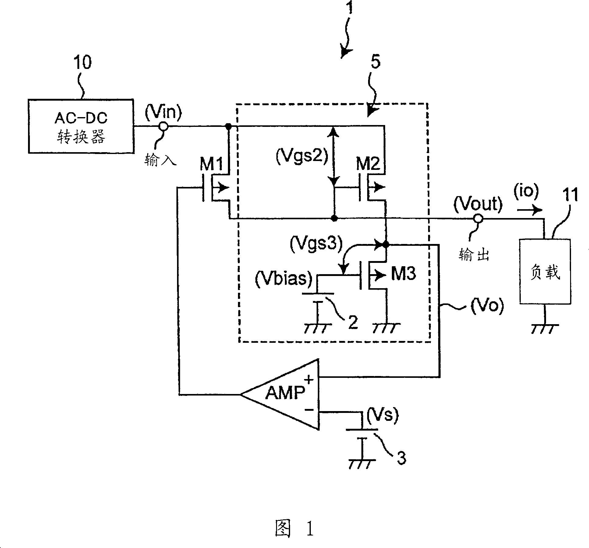
[0023] FIG. 1 shows an example circuit of a power supply device according to a first embodiment of the present invention.

[0024] In FIG. 1, a power supply device 1 inputs an output voltage from an AC-DC converter 10 as an input voltage Vin to an input terminal IN, and the power supply device 1 outputs an output voltage Vout from an output terminal OUT to a load 11 through a switching element M1. .

[0025] The power supply device 1 includes a bias voltage generating circuit 2, a reference voltage generating circuit 3, PMOS transistors M1 to M3, and an operational amplifier circuit AMP. It should be noted that the PMOS transistor M2 constitutes a first MOS transistor, the PMOS transistor M3 constitutes a second MOS transistor, the reference voltage generating circuit 3 and the operational amplifier circuit AMP constitute a control circuit, and the operational amplifier circuit AMP constitutes a comparator circuit.

[0026] The switching element M1 described above includes a ...


PUM


Abstract

A power-supply apparatus for outputting a voltage via one or more switching elements is disclosed. The apparatus includes a voltage-generating circuit for generating an output, voltage Vo proportional to a voltage between an input end and an output end of the switching element, and a control circuit for controlling an operation of the switching element depending on the output voltage Vo. The control circuit causes the switching element to reduce an output current when the output voltage Vo exceeds a predetermined voltage Vs.

Description

technical field [0001] The present invention generally relates to a power supply device including a protection circuit for preventing overcurrent output, and in particular to a power supply device including such a protection circuit when applied to a switching element for outputting a voltage input to an input terminal When the voltage reaches a predetermined voltage or higher, the protection circuit cuts off the switching element for protection purposes. Background technique [0002] In the conventional power supply device shown in FIG. 8, a circuit for protecting a switching element outputs an output voltage Vout from an output terminal OUT according to an input voltage Vin input to an input terminal IN. A circuit is generally used to compare the voltage drop due to the fixed resistor Ra in series with the PMOS transistor Ma constituting the switching element with the reference voltage Vs. When the voltage drop as described above exceeds the reference voltage Vs, the circ...

Claims


Application Information

Patent Timeline
Patent Type & Authority Applications(China)
IPC IPC(8): H03K17/08G05F1/56H03K17/687H02M7/217
CPCH02M2001/007H02M7/2176H02M1/007H03K17/08
Inventor 西田淳二
Owner RICOH KK
Why Eureka
Try Eureka