
Stator punching sheet, stator core, stator, motor and air conditioning device

A technology of stator punching and stator iron core is applied in the fields of motors and air conditioners, stator punching, stator and stator iron core, and can solve the problems of structural strength of connecting bridges and so on.

Pending Publication Date: 2021-01-22
ZHUHAI GREE REFRIGERATION TECH CENT OF ENERGY SAVING & ENVIRONMENTAL PROTECTION
View PDF0 Cites 0 Cited by
  • Summary
  • Abstract
  • Description
  • Claims
  • Application Information

AI Technical Summary

Problems solved by technology

[0005] In order to solve the technical problem that the structural strength of the connecting bridge of the existing chain-type stator core is low, the main purpose of this application is to provide a stator punch, a stator core, a stator, a motor and an air conditioner

Method used


Image

  • Stator punching sheet, stator core, stator, motor and air conditioning device
  • Stator punching sheet, stator core, stator, motor and air conditioning device
  • Stator punching sheet, stator core, stator, motor and air conditioning device

Examples


Embodiment 1

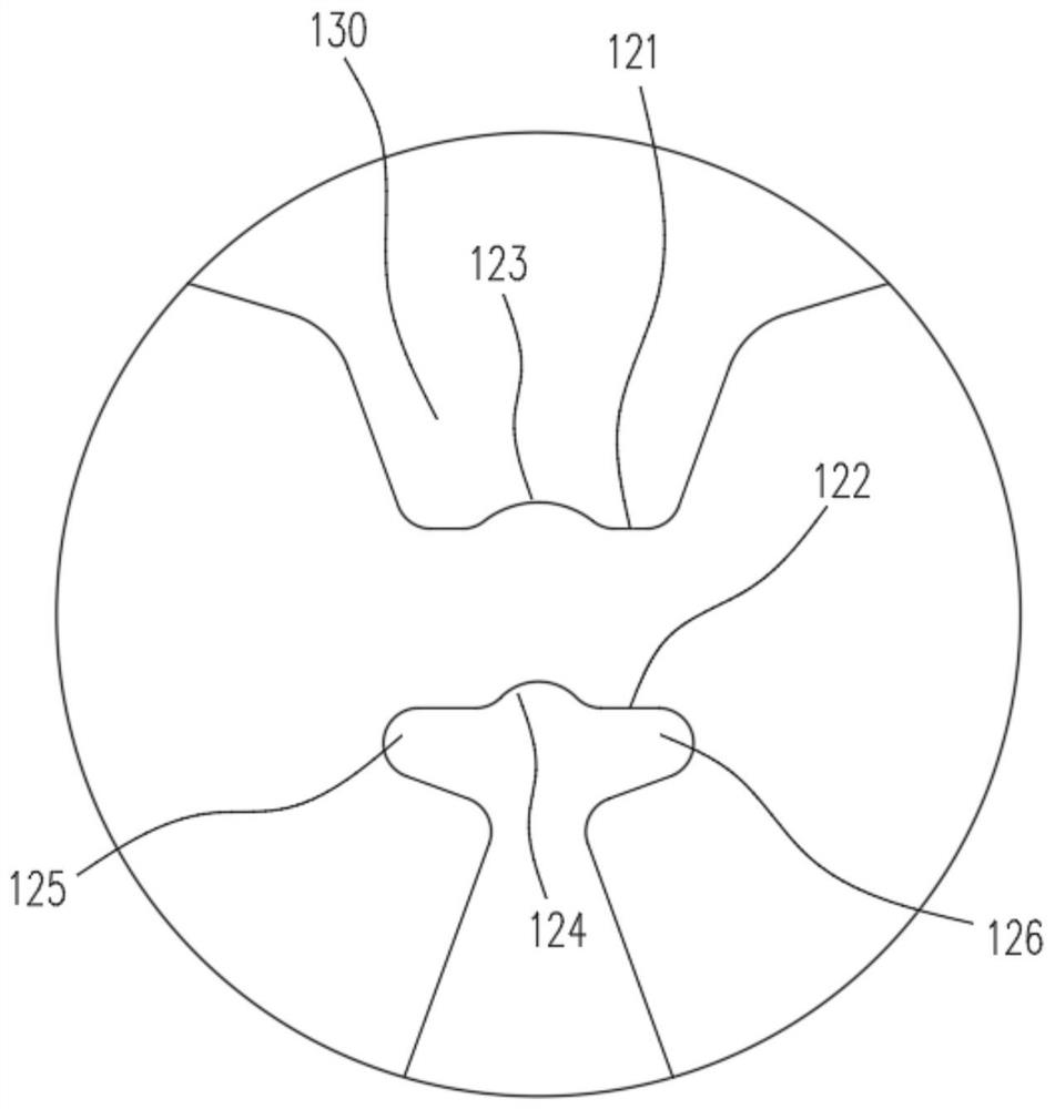
[0054] combine Figure 1-5 as shown, Figure 1-5 The connecting bridge 120 of the middle stator punching sheet and the punching sheet unit 110 have the same structure.

[0055] Such as figure 1 Among them, the stator stamping includes a plurality of stamping units 110 connected in sequence, and a connecting bridge 120 is provided between two adjacent stamping units 110, and the outer peripheral side of each stamping unit 110 is provided with a The positioning groove for positioning, the positioning groove may be a groove structure. Three buckle points 113 are also arranged on the punching unit 110, and the buckle points 113 are rectangular holes. In this embodiment, the punching unit 110 can adopt one of 0.25mm, 0.3mm, 0.35mm, and 0.5mm thick specifications. It is processed from a kind of electrical steel strip plate, and the lamination forming of the stamping monomer 110 is facilitated through the buckle point 113.

[0056] figure 1 It is a schematic diagram of the resul...

Embodiment 2

[0064] combine Figure 6-8 as shown, Image 6 The middle is a schematic diagram of the structure of the second stator stamping in the solution of the present application. In this embodiment, the tooth end of the stamping unit 110 is an arc-shaped structure.

[0065] Such as Image 6 Among them, the stator stamping includes a plurality of stamping units 110 connected in sequence, and a connecting bridge 120 is provided between two adjacent stamping units 110, and the outer peripheral side of each stamping unit 110 is provided with a The positioning groove for positioning, the positioning groove may be a groove structure. Three buckle points 113 are also arranged on the punching unit 110, and the buckle points 113 are rectangular holes. In this embodiment, the punching unit 110 can adopt one of 0.25mm, 0.3mm, 0.35mm, and 0.5mm thick specifications. It is processed from a kind of electrical steel strip plate, and the lamination forming of the stamping monomer 110 is facilitate...

Embodiment 3

[0071] combine Figure 9-11 as shown, Figure 9 The middle is a schematic diagram of the structure of the third stator punching in this application scheme. In this embodiment, the tooth end of the punching unit 110 is an arc-shaped structure, and the root of the tooth of the punching unit 110 is a straight-edge structure, which is convenient Die stamping and winding equipment line up to improve the utilization rate of iron core materials.

[0072] Such as Figure 9 Among them, the stator stamping includes a plurality of stamping units 110 connected in sequence, and a connecting bridge 120 is provided between two adjacent stamping units 110, and the outer peripheral side of each stamping unit 110 is provided with a The positioning groove for positioning, the positioning groove may be a groove structure. Three buckle points 113 are also arranged on the punching unit 110, and the buckle points 113 are rectangular holes. In this embodiment, the punching unit 110 can adopt one o...


PUM


Abstract

The invention generally relates to the technical field of motors, in particular to a stator punching sheet, a stator core, a stator, a motor and an air conditioning device. The stator punching sheet comprises a plurality of punching sheet single bodies which are connected in sequence, and a connecting bridge is arranged between every two adjacent punching sheet single bodies; grooves are formed between the radial outer side of the connecting bridge and two adjacent punching sheet single bodies, the connecting bridge comprises a first side end face located on the radial outer side and a secondside end face located on the radial inner side, and the first side end face comprises a first buffer surface protruding towards the radial outer side. The second side end face comprises a second buffer surface recessed towards the outer side in the radial direction, and the first buffer surface and the second buffer surface are used for bending buffer of the connecting bridge to reduce damage of the connecting bridge during circle forming. According to the scheme, the stator punching sheet can be folded reversely, wire winding is convenient, and the wire winding full tank rate is improved, andthe first buffer surface can reduce the bending of the connecting bridge when the stator punching sheet is reversely folded.

Description

technical field [0001] The present application generally relates to the technical field of motors, and in particular, relates to a stator punch, a stator core, a stator, a motor and an air conditioner. Background technique [0002] With the country's requirements for the energy efficiency level of household products such as air conditioners and refrigerators, and the improvement of people's living standards, the compressor is the core component of the refrigeration device. The chain stator punching in the prior art includes multiple sequentially connected punching units. body, and two adjacent punching pieces are connected by a yoke connecting bridge. [0003] However, the existing connecting bridge has a straight-edge structure, which is easily deformed and damaged when the stator core is rounded, and the chain-type stator punches are easily broken due to reciprocating bending, and the structural strength of the connecting bridge is weak. Contents of the invention [000...

Claims


Application Information

Patent Timeline
Patent Type & Authority Applications(China)
IPC IPC(8): H02K1/14H02K1/18
CPCH02K1/148H02K1/185H02K2213/03
Inventor 魏会军陈世国朱红伟
Owner ZHUHAI GREE REFRIGERATION TECH CENT OF ENERGY SAVING & ENVIRONMENTAL PROTECTION
Learn More