
Ultra-high voltage transmission line security inspection equipment

A transmission line and UHV technology, applied in the field of UHV transmission line security inspection equipment, can solve problems such as power supply accidents, inconvenient maintenance work, pedestrian injuries, etc., and achieve the effects of enhancing earthquake resistance, avoiding damage, and reinforcing slip resistance

Active Publication Date: 2021-01-22
锦州中物科技有限公司
View PDF22 Cites 3 Cited by
  • Summary
  • Abstract
  • Description
  • Claims
  • Application Information

AI Technical Summary

Problems solved by technology

Because the distance between the iron towers is relatively long, the large-span high-voltage wires between the iron towers are prone to repeated pulling and twisting under harsh field conditions, resulting in local tearing on the surface of the high-voltage wires. If not found and repaired in time , eventually resulting in accidental breakage of high-voltage wires, power supply accidents, affecting residents and industrial power consumption, and causing damage to local animals and plants on the ground, and even pedestrians
[0003] At present, the common UHV transmission line security inspection method on the market generally uses the staff to climb to the location where the fault occurs for security inspection and maintenance, but working on the high-voltage power line is a very dangerous thing, and the staff need to consume a lot of energy when walking on the high-voltage power line. Physical strength, it is difficult to concentrate on maintenance work, and during maintenance, maintenance tools need to be carried, and it is not conducive for the staff to carry maintenance tools on the body, which is not conducive to action on high-voltage wires, and it is not convenient for maintenance work

Method used


Image

  • Ultra-high voltage transmission line security inspection equipment
  • Ultra-high voltage transmission line security inspection equipment
  • Ultra-high voltage transmission line security inspection equipment

Examples


Embodiment

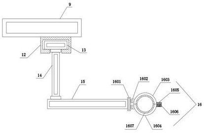
[0035] see Figure 1-6 , a UHV transmission line security inspection equipment, comprising a base 1, a moving mechanism 2 is fixedly installed on the bottom of the base 1, a stabilizing mechanism 3 is fixedly installed on the left and right sides of the base 1, and the left and right sides of the top of the base 1 Both sides are fixedly connected with supporting columns 4, and the tops of the supporting columns 4 are provided with installation grooves 5, and hydraulic cylinders 6 are fixedly installed inside the installation grooves 5, and the output ends of the hydraulic cylinders 6 are fixedly connected There is a working bottom plate 7, four corners of the top of the working bottom plate 7 are fixedly connected with upright columns 8, and the tops of the upright columns 8 are fixedly connected with a working top plate 9, and the top of the working top plate 9 is fixedly installed with a solar power generation mechanism 10. Guardrails 11 are fixedly connected between the col...


PUM


Abstract

The invention discloses ultra-high voltage transmission line security inspection equipment, and belongs to the field of electric power overhaul. The equipment comprises a base, a moving mechanism is fixedly installed at the bottom of the base, stabilizing mechanisms are fixedly installed on the left and right sides of the base, and supporting columns are fixedly connected to the left and right sides of the top of the base. Mounting grooves are formed in the tops of the supporting columns correspondingly, hydraulic cylinders are fixedly mounted in the mounting grooves correspondingly, a workingbottom plate is fixedly connected to the output ends of the hydraulic cylinders correspondingly, stand columns are fixedly connected to the four corners of the top of the working bottom plate correspondingly, and a working top plate is fixedly connected to the tops of the stand columns correspondingly. A solar power generation mechanism is fixedly mounted at the top of the working top plate, anda protective fence is fixedly connected between the stand columns. By arranging extension arms, the extension arms can help a worker to carry out maintenance work, and by arranging clamping mechanisms, the clamping mechanisms are used for fixing the high-voltage lines, so that the worker can carry out maintenance conveniently.

Description

technical field [0001] The invention relates to the field of electric power inspection and maintenance, and more specifically relates to a safety inspection device for UHV transmission lines. Background technique [0002] UHV transmission lines refer to the transmission of electric energy at a voltage level of 800 kV and above for direct current and 1,000 kV and above for alternating current. UHV transmission is developed on the basis of EHV transmission, and its purpose is to continue to improve transmission capacity, realize high-power medium and long-distance transmission, and realize long-distance power system interconnection to build a combined power system. Long-distance transmission of high-voltage electric energy in the field requires the use of high-voltage wires, which are suspended through iron towers. Because the distance between the iron towers is relatively long, the large-span high-voltage wires between the iron towers are prone to repeated pulling and twisti...

Claims


Application Information

Patent Timeline
IPC IPC(8): H02G1/02B66F11/04B66F13/00B66F17/00H02S40/00
CPCH02G1/02B66F11/04B66F13/00B66F17/006H02S40/00Y02E10/50
Inventor 不公告发明人
Owner 锦州中物科技有限公司
Learn More