
Monocular vision-based detection method for detecting spatial position of part

A technology of spatial position and monocular vision, applied in the field of robot vision, can solve the problems of limited measurement range, inapplicability, and sensitivity to ambient light of the camera baseline, achieve good horizontal detection effect and vertical detection effect, reduce horizontal error and vertical Error, the effect of reducing radial distortion

Pending Publication Date: 2021-01-22
SHANGHAI UNIV OF ENG SCI
View PDF4 Cites 9 Cited by
  • Summary
  • Abstract
  • Description
  • Claims
  • Application Information

AI Technical Summary

Problems solved by technology

[0003] The traditional part detection system based on binocular vision detection technology has its advantages: low cost, suitable for both indoors and outdoors, etc., but also has the following disadvantages: it is very sensitive to ambient light, not suitable for scenes that are monotonous and lack of texture, and has high computational complexity. And the camera baseline limits the measurement range
It can be seen that the feature matching of binocular vision detection technology is relatively cumbersome.

Method used


Image

  • Monocular vision-based detection method for detecting spatial position of part
  • Monocular vision-based detection method for detecting spatial position of part
  • Monocular vision-based detection method for detecting spatial position of part

Examples


Embodiment Construction

[0046]The present invention will be further described below in combination with specific embodiments. It should be understood that these examples are only used to illustrate the present invention and are not intended to limit the scope of the present invention. In addition, it should be understood that after reading the teachings of the present invention, those skilled in the art can make various changes or modifications to the present invention, and these equivalent forms also fall within the scope defined by the appended claims of the present application.

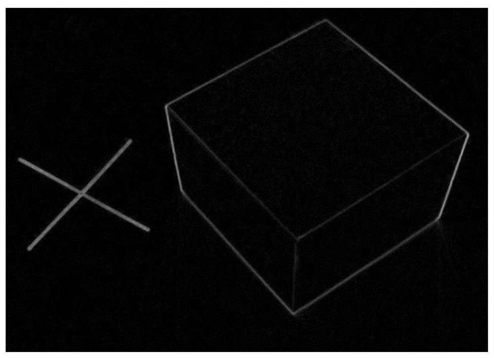
[0047] A detection method based on monocular vision to detect the spatial position of parts, such as figure 1 As shown, the steps are as follows:

[0048] (1) Calibrate and calibrate the camera;

[0049] The camera is a monocular camera;

[0050] The specific process of calibration and calibration is as follows: first, the camera is used to align the calibration plate (the material of the calibration plate is aluminum ...


PUM


Abstract

The invention relates to a monocular vision-based detection method for detecting spatial position of parts. The detection method comprises the following steps: (1) calibrating and calibrating a camera; (2) preparing for establishment of world coordinates of the image; (3) preparing for image binaryzation; (4) carrying out image binarization; (5) establishing world coordinates of the image; (6) performing image edge detection; (7) accurately detecting a straight line in the image; (8) obtaining two-dimensional coordinates of the corner points; (9) acquiring three-dimensional coordinates of thecorner points; (10) calculating errors. The monocular vision technology is used for detecting the position of the object, the transverse error and the longitudinal error of the object block are reduced, the good object block transverse detection effect and the good object block longitudinal detection effect are achieved, cube corner point positioning can be achieved through the technology, then the method can be applied to the cube splicing process, and more accurate splicing and welding are achieved.

Description

technical field [0001] The invention belongs to the technical field of robot vision, and relates to a detection method for detecting the spatial position of a part based on monocular vision. Background technique [0002] The binocular vision technology has been developed for several years. In the binocular solution, the two lenses should theoretically be exactly the same, because once there is a difference, the accuracy of the measurement will be greatly reduced. The binocular camera, due to its own ranging principle, requires the error between the two lenses to be as small as possible. If the two lenses each have an error of about 5%, it will be much more difficult for the post-adjustment algorithm, and the certainty cannot be guaranteed. The binocular camera also has the problem of placement. The distance between the two lenses is between 10 and 20cm. This distance needs to be very accurate, because it will directly affect the accuracy of the distance measurement. [00...

Claims


Application Information

Patent Timeline
Patent Type & Authority Applications(China)
IPC IPC(8): G06T7/00G06T7/13G06T7/11G06T7/136G06T7/73G06T7/80
CPCG06T7/0004G06T7/13G06T7/11G06T7/136G06T7/73G06T7/80G06T2207/10004G06T2207/30164
Inventor 孟金旭单鸿涛袁翔林熊玺赵文洁孟帆海关同昊廖云峰
Owner SHANGHAI UNIV OF ENG SCI
Learn More