
Circuit design transplanting method

A circuit design and sub-module technology, applied in the field of integrated circuit design, can solve the problems of difficulty in passing the simulation sign-off verification, obstacles, and the influence of parasitic parameters is becoming more and more serious, and achieves the effect of solving the difficulty of transplantation.

Pending Publication Date: 2021-01-22
杨家奇
View PDF0 Cites 0 Cited by
  • Summary
  • Abstract
  • Description
  • Claims
  • Application Information

AI Technical Summary

Problems solved by technology

[0002] In the 2000s, the transplantation method of traditional circuit design is to first consider only the circuit characteristics for transplantation, and then start to do automatic layout processing. It is getting more and more serious, resulting in only considering the layout of the circuit characteristics after transplantation, the parasitic parameters are difficult to predict in advance due to the complexity of the process, and it is difficult to pass the post-simulation signoff verification, making this method in advanced technology, where the parasitic parameters are seriously affected In the 2010s, the impact of layout design rules began to be considered, mainly considering the matching of components, including: the matching of electrical parameters of components and the matching of layout design rules (the same scaling of components The matching of all circuit circuits is achieved by the matching of components, but the transplantation method of the existing circuit design still has the following problems:
[0005] In short, the traditional method will make it difficult to implement "circuit design transplantation" due to the complexity of advanced engineering, circuit complexity, and different scaling ratios of components.

Method used


Image

  • Circuit design transplanting method
  • Circuit design transplanting method

Examples


Embodiment Construction

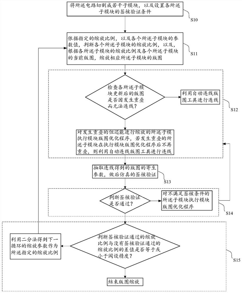
[0036] The transplantation method of the circuit design proposed by the present invention will be further described in detail below in conjunction with the accompanying drawings and specific embodiments. The advantages and features of the present invention will become clearer from the following description. It should be noted that all the drawings are in a very simplified form and use imprecise scales, and are only used to facilitate and clearly assist the purpose of illustrating the embodiments of the present invention. In addition, the structures shown in the drawings are often a part of the actual structure. In particular, each drawing needs to display different emphases, and sometimes uses different scales.

[0037] like figure 1 As shown, this embodiment provides a method for transplanting a circuit design, and the method for transplanting a circuit design includes the following steps:

[0038] S10, cutting the circuit into several sub-modules, and setting a sign-off v...


PUM


Abstract

The invention provides a circuit design transplanting method, which comprises the following steps of: cutting a circuit into a plurality of sub-modules, and setting sign-off verification conditions ofthe sub-modules; according to the layout mode of the original layout, zooming each sub-module, and if overlapping is caused by different layout zooming proportions, carrying out optimization reduction in the sub-modules for the first time; if the optimization is successful, carrying out post-simulation sign-off, and if the optimization is unsuccessful, carrying out secondary optimization of the interior of the sub-module, taking the post-simulation sign-off as a condition to amplifying key components moderately, wherein if overlapping is not caused after the layout is amplified, it representsthat the scaling is feasible, and if overlapping occurs, it represents that the scaling is carried out; and continuously performing reducing by using a dichotomy to obtain successful and failed zoomratios.

Description

technical field [0001] The invention relates to the technical field of integrated circuit design, in particular to a method for transplanting circuit design. Background technique [0002] In the 2000s, the transplantation method of traditional circuit design is to first consider only the circuit characteristics for transplantation, and then start to do automatic layout processing. It is getting more and more serious, resulting in only considering the layout of the circuit characteristics after transplantation, the parasitic parameters are difficult to predict in advance due to the complexity of the process, and it is difficult to pass the post-simulation signoff verification, making this method in advanced technology, where the parasitic parameters are seriously affected In the 2010s, the impact of layout design rules began to be considered, mainly considering the matching of components, including: the matching of electrical parameters of components and the matching of layou...

Claims


Application Information

Patent Timeline
IPC IPC(8): G06F30/398G06F30/392
CPCG06F30/398G06F30/392
Inventor 王韦棠
Owner 杨家奇
Learn More