
FPGA remote online debugging method, device and system based on optical fiber communication

A technology of optical fiber communication and debugging method, which is applied in the direction of radio wave measurement system, optical fiber transmission, instruments, etc., can solve the problems of maintenance personnel's personal safety not being guaranteed, long-distance transmission signal interference, and the number of signal channels being limited, etc., to achieve Solve the effect that personal safety cannot be guaranteed

Active Publication Date: 2021-01-22
四川九洲空管科技有限责任公司
View PDF21 Cites 2 Cited by
  • Summary
  • Abstract
  • Description
  • Claims
  • Application Information

AI Technical Summary

Problems solved by technology

[0010] The object of the present invention is to overcome the deficiencies in the prior art, provide a kind of FPGA remote online debugging method, device and system based on optical fiber communication, provide a kind of effective means for the remote debugging of secondary radar system, solve the problem during secondary radar work The problem of long-distance transmission of online debugging signals and the signal's susceptibility to interference solves the problem of limited number of signal channels for machine-scanning radar rotary joints, and solves the problem of personal safety of maintenance personnel not being guaranteed during maintenance, making debugging / maintenance work anytime and anywhere Can be carried out, safe, efficient, simple, convenient, etc.

Method used


Image

  • FPGA remote online debugging method, device and system based on optical fiber communication
  • FPGA remote online debugging method, device and system based on optical fiber communication
  • FPGA remote online debugging method, device and system based on optical fiber communication

Examples


Embodiment Construction

[0033] All features disclosed in all embodiments in this specification (including any appended claims, abstract and drawings), or steps in all methods or processes implicitly disclosed, except for mutually exclusive features and / or steps, can be used as Combining and / or extending, replacing in any way.

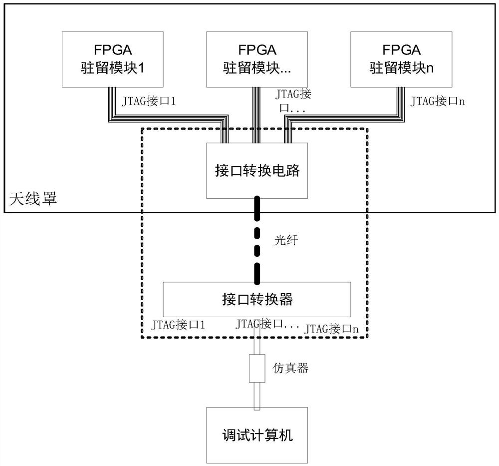
[0034] like Figure 1~3 Shown, a kind of FPGA remote online debugging method based on optical fiber communication, comprises steps:

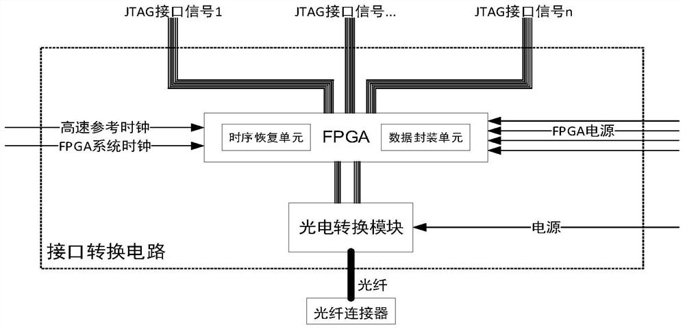
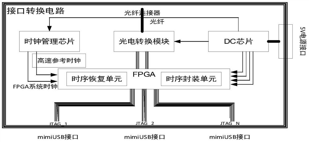
[0035] S1, establish an FPGA remote online debugging system based on optical fiber communication, the system includes a radome with an interface conversion circuit, an interface converter, and a debugging computer; the radome with an interface conversion circuit is connected to the interface converter through an optical fiber, and the interface conversion The device is connected with the debugging computer;

[0036] S2, the data encapsulation unit in the FPGA module encapsulates the JTAG interface transmission channel signal, and transmits it ...


PUM


Abstract

The invention discloses an FPGA remote online debugging method, device and system based on optical fiber communication. The method comprises the steps of: S1, building an FPGA remote online debuggingsystem based on optical fiber communication, wherein the system comprises an antenna housing provided with an interface conversion circuit, an interface converter, and a debugging computer; the antenna housing provided with the interface conversion circuit is connected with the interface converter through an optical fiber, and the interface converter is connected with the debugging computer. The invention provides an effective means for remote debugging of a secondary radar system, solves the problems of long-distance transmission of online debugging signals and easy interference of the signals in the working period of a secondary radar, solves the problem that the number of signal channels of a mechanical scanning radar rotating joint is limited, solves the problem that the personal safety of maintenance personnel cannot be guaranteed in the maintenance period, debugging / maintenance work can be carried out anytime and anywhere, and safety, high efficiency, simplicity, convenience andthe like are realized.

Description

technical field [0001] The present invention relates to the technical field of radar system online debugging, and more specifically, relates to an FPGA remote online debugging method, device and system based on optical fiber communication. Background technique [0002] The conventional online debugging method is that the maintenance personnel connect the maintenance computer and the FPGA through an emulator to carry out online debugging at a place close to the equipment. [0003] Part of the signal processing of the secondary radar needs to be close to the antenna unit, and due to antenna erection requirements and personal safety reasons, once the erection is completed, personnel cannot climb onto the turntable at will. [0004] The antenna of the radar is set up high, which is not suitable for personnel to stay for a long time. Maintenance personnel usually concentrate on debugging, and may forget the danger of their own environment and cause safety accidents; it is necessa...

Claims


Application Information

Patent Timeline
Patent Type & Authority Applications(China)
IPC IPC(8): G01S7/40H04B10/25
CPCG01S7/40
Inventor 杨见陈伟郭小杰
Owner 四川九洲空管科技有限责任公司
Learn More