
A spray tower for oil fume treatment system

A technology for oil fume treatment and spray tower, which is applied in the direction of using tools for cleaning, cleaning methods and utensils, and the use of liquid separators, etc. Guaranteed normal operation

Active Publication Date: 2021-11-19
杭州临安杨氏电缆材料有限公司
View PDF0 Cites 0 Cited by
  • Summary
  • Abstract
  • Description
  • Claims
  • Application Information

AI Technical Summary

Problems solved by technology

As the use time of the orifice plate increases, the impurities on the orifice plate will accumulate more and more, which not only affects the normal flow of dusty exhaust gas, but also corrodes the orifice plate and reduces the service life of the orifice plate. Therefore, it is necessary to arrange workers regularly Use cleaning tools to clean the impurities on the orifice plate, but this method of manually cleaning the orifice plate is time-consuming and laborious, which brings a lot of inconvenience to the workers.

Method used


Image

  • A spray tower for oil fume treatment system
  • A spray tower for oil fume treatment system
  • A spray tower for oil fume treatment system

Examples


Embodiment Construction

[0032] The following is attached Figure 1-3 The application is described in further detail.

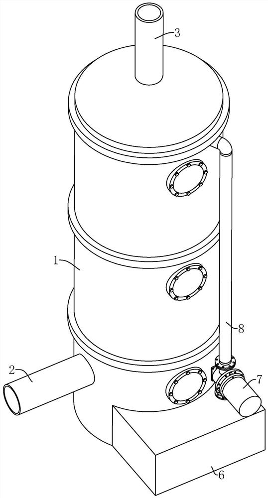
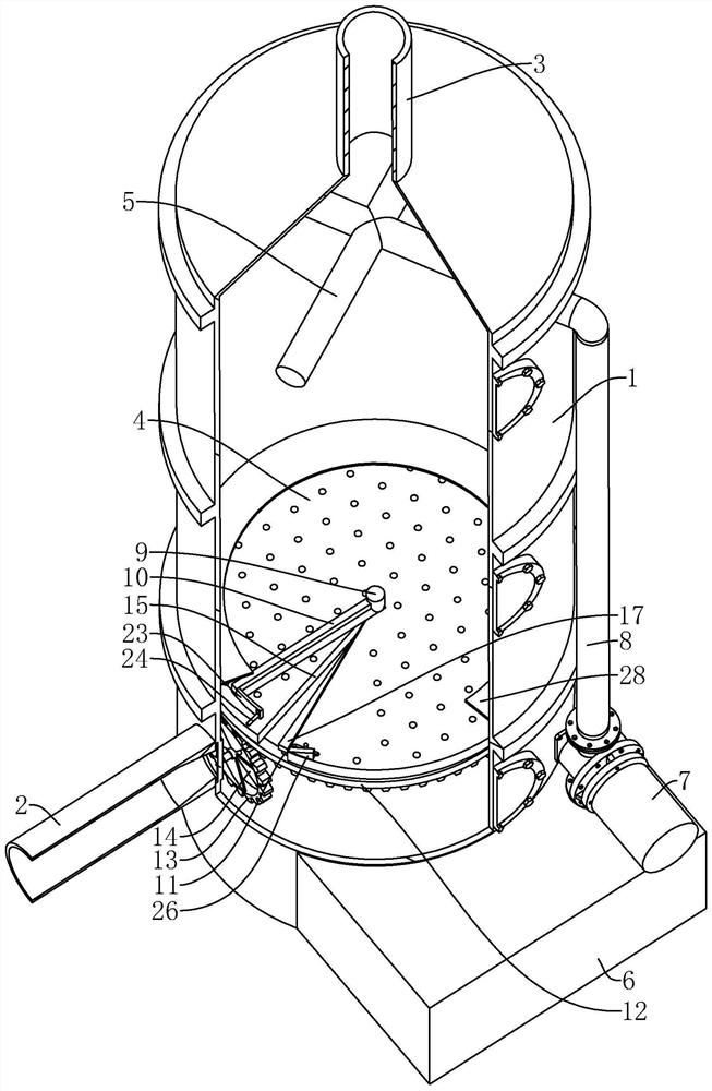
[0033] refer to figure 1 and figure 2 , a spray tower for oil fume treatment system, including a hollow tower body 1, an air inlet pipe 2 and an air outlet pipe 3 that are fixedly connected to the tower body 1 and communicated with the inside of the tower body 1, and the air outlet pipe 3 is located in the air inlet pipe 2; the spray tower also includes an orifice 4 installed in the tower body 1 and between the inlet pipe 2 and the outlet pipe 3, the spray pipe 5 above the orifice 4, and the A water tank 6 , a water pump 7 placed in the water tank 6 , and a water delivery pipe 8 connected between the water pump 7 and the spray pipe 5 . The spray pipe 5, the water tank 6, the water pump 7 and the water delivery pipe 8 constitute the spray mechanism. When the spray tower is working, the water pump 7 pumps the water in the water tank 6 to the spray pipe 5 for spraying from top to b...


PUM


Abstract

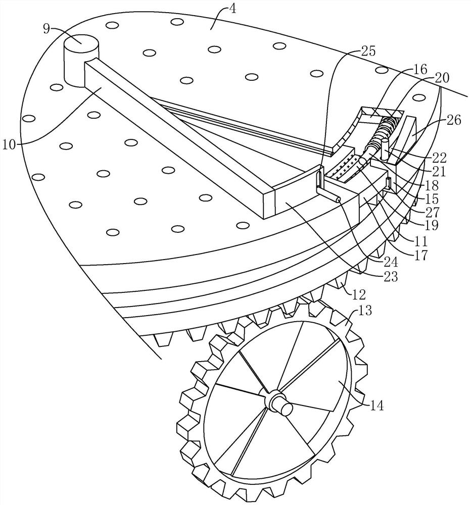
This application relates to the field of exhaust gas treatment, especially to a spray tower for oil fume treatment system, including a tower body with an inlet pipe and an outlet pipe, a spray mechanism and an orifice plate. The shaft is vertical to the shaft, and the upper scraper and the lower scraper are fixedly connected to the shaft to contact the upper and lower surfaces of the orifice plate; the tower body is also equipped with a rotating mechanism that uses the wind force of the exhaust gas to rotate the shaft; There is a fan-shaped groove in the same radial direction as the orifice plate and connected to the upper and lower surfaces of the orifice plate. A rotating groove is provided on one side wall of the fan-shaped groove, and a rotating plate is slidingly embedded in the rotating groove. The spring of the rotating groove; the orifice plate is also equipped with a self-starting mechanism that automatically opens the rotating groove when the upper scraper is close to the rotating groove. This scheme greatly facilitates workers to clean impurities on the orifice plate, ensures the shunting effect of the orifice plate on exhaust gas, and improves the dust removal effect on exhaust gas.

Description

technical field [0001] The present application relates to the field of waste gas treatment, in particular to a spray tower used in a fume treatment system. Background technique [0002] In the production process of cable materials, there is a process of refining raw rubber and compounding agents into rubber compound, which is called compounding for short. Exhaust gas with soot is often produced during the mixing process, and these exhaust gases need to be purified before being discharged into the air. Purification principle of exhaust gas: inject the exhaust gas with oil fume into the high-voltage electrostatic field, under the action of the high-voltage electric field, the oil fume gas is ionized, the oil mist is charged, and most of them are degraded and carbonized; Under the action of airflow, it moves towards the positive and negative plates of the electric field, and the tiny oil particles will be collected on the plates and flow to the oil collecting pan under the act...

Claims


Application Information

Patent Timeline
Patent Type & Authority Patents(China)
IPC IPC(8): B01D47/06B01D50/00B01D46/10B01D46/00B08B1/04B08B13/00
CPCB01D47/06B01D46/10B08B1/005B08B1/04B08B13/00B01D46/681B01D50/60
Inventor 蒋舒
Owner 杭州临安杨氏电缆材料有限公司
Learn More