Expansion instrument for laparoscopic surgery
A laparoscopic technique for surgery, which is applied in the field of medical devices, can solve the problems of human discomfort and inconvenient use, and achieve the effect of facilitating surgical operations, avoiding misuse, and strong practicability
- Summary
- Abstract
- Description
- Claims
- Application Information
AI Technical Summary
Problems solved by technology
Method used
Image
Examples
Embodiment 1
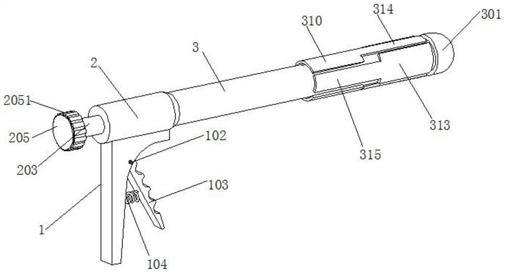
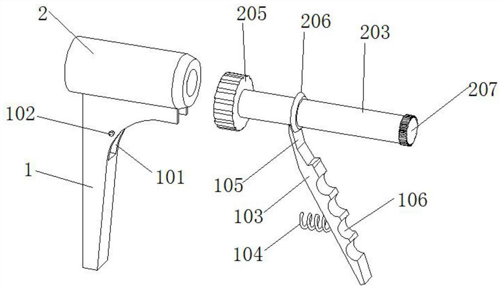
[0033] This embodiment 1 discloses a laparoscopic surgery with a distraction instrument, refer to the attached figure 1 , attached figure 2 And attached image 3 , its main structure includes a hand-held part 1, and the inner side of the hand-held part 1 is provided with a rotating groove 101, and a pin shaft 102 is arranged in the rotating groove 101, and a hand-holding rod 103 is connected to the rotating shaft 102, and the handle rod 103 There are 3 to 4 arc-shaped finger grip grooves 106 on the outer surface of the body. And a first spring 104 is connected between the handle bar 103 and the inner wall of the rotating groove 101 , and the reset function can be realized through the first spring 104 . The upper end of the handle bar 103 is provided with a pawl 105, and the upper end of the pawl 105 is provided with an arc-shaped slot (not marked in the figure), and the arc-shaped slot (not marked in the figure) can be connected with the first rotating rod behind. 203 oute...
Embodiment 2
[0038] Embodiment 2 discloses an improved distraction instrument for laparoscopic surgery based on Embodiment 1. Refer to the attached figure 1 , attached figure 2 And attached image 3 , its main structure includes a hand-held part 1, and the inner side of the hand-held part 1 is provided with a rotating groove 101, and a pin shaft 102 is arranged in the rotating groove 101, and a hand-holding rod 103 is connected to the rotating shaft 102, and the handle rod 103 There are 3 to 4 arc-shaped finger grip grooves 106 on the outer surface of the body. And a first spring 104 is connected between the handle bar 103 and the inner wall of the rotating groove 101 , and the reset function can be realized through the first spring 104 . The upper end of the handle bar 103 is provided with a pawl 105, and the upper end of the pawl 105 is provided with an arc-shaped slot (not marked in the figure), and the arc-shaped slot (not marked in the figure) can be connected with the first rotati...
PUM
 Abstract
Description
Claims
Application Information
 - Generate Ideas
- Intellectual Property
- Life Sciences
- Materials
- Tech Scout
- Unparalleled Data Quality
- Higher Quality Content
- 60% Fewer Hallucinations
Browse by: Latest US Patents, China's latest patents, Technical Efficacy Thesaurus, Application Domain, Technology Topic, Popular Technical Reports.
© 2025 PatSnap. All rights reserved.Legal|Privacy policy|Modern Slavery Act Transparency Statement|Sitemap|About US| Contact US: help@patsnap.com


