Bipolar plate structure capable of being used for fuel cell, fuel cell and fuel cell vehicle
A fuel cell and bipolar plate technology, which is applied in fuel cells, power system fuel cells, circuits, etc., can solve the problems of increasing the overall weight of the battery stack, reducing power density, and insufficient, and improving the reaction uniformity and the stack. Power density, effect of increasing flow rate and activity, reducing process cost
- Summary
- Abstract
- Description
- Claims
- Application Information
AI Technical Summary
Problems solved by technology
Method used
Image
Examples
no. 1 example
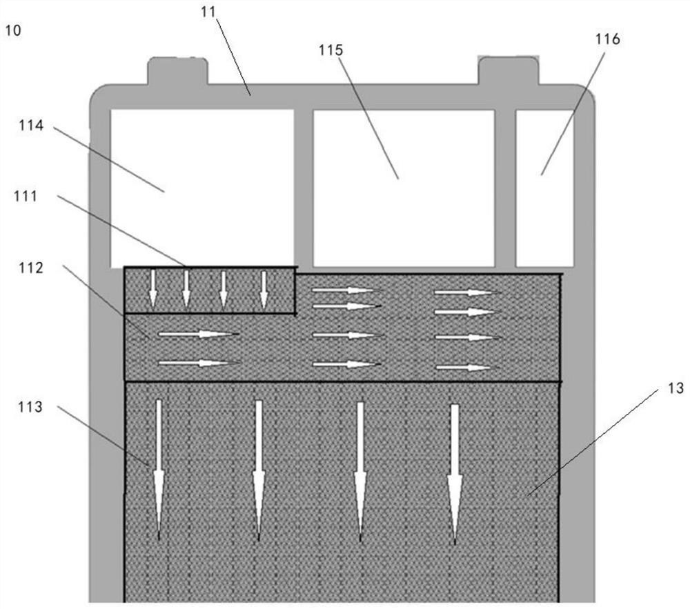
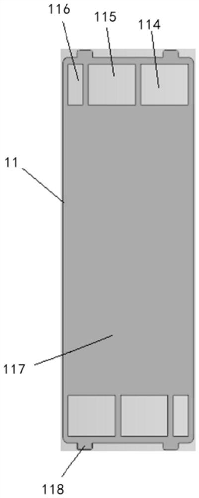
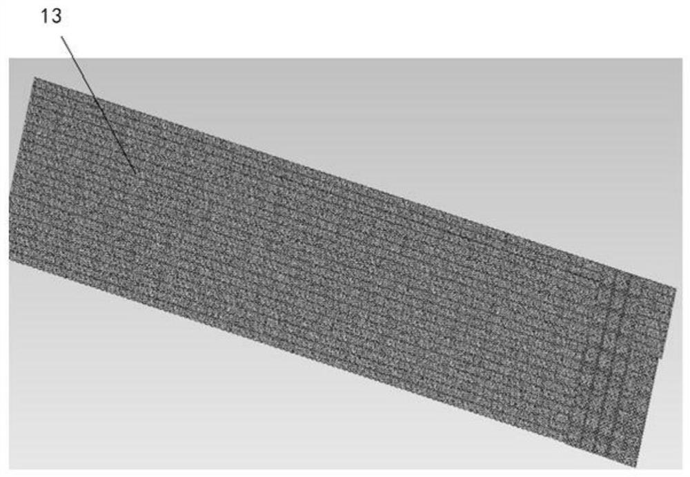
[0046] figure 1 A bipolar plate structure 10 applicable to a fuel cell according to an embodiment of the present disclosure is shown. Such as figure 1 As shown, the bipolar plate structure 10 includes a substrate 11 ( figure 1 The middle part shows the substrate 11) and the mesh structure 13. There are multiple flow regions for fluids on the substrate 11 , including but not limited to an inlet region 111 , a transition region 112 and a reaction region 113 . Mesh structure 13 has a mesh, the size of the length direction of the mesh is greater than the size of the width direction (described in detail below), the mesh structure 13 is arranged on the base, forming at least one of the plurality of flow areas , for example forming the inlet zone 111 , the transition zone 112 and the reaction zone 113 . Described in detail below.
[0047] figure 2 The structure of the substrate 11 is shown. The base 11 is, for example, a metal substrate. Metal substrates have obvious advanta...
no. 2 example
[0060] The second embodiment of the present disclosure relates to a method 200 for preparing a bipolar plate structure that can be used in fuel cells, the following reference Figure 7 describe.
[0061] Such as Figure 7 As shown, method 200 includes:
[0062] In step S201, a substrate is provided or prepared. The substrate, such as the substrate 11 described above in the first embodiment section, has a plurality of flow regions for fluids thereon, including but not limited to inlet regions, transition regions and reaction regions.
[0063] In step S202, a network structure is provided or prepared. The mesh structure is, for example, the mesh structure 13 described in the first embodiment above, which has mesh holes, and the size of the mesh holes in the length direction is larger than the size in the width direction.
[0064] In step S203, the mesh structure is disposed on the substrate to form at least one of the plurality of flow regions, thereby forming a bipolar plat...
no. 3 example
[0071] The third embodiment of the present disclosure also relates to a bipolar plate structure applicable to a fuel cell. The third embodiment is a modification of the first embodiment, so for the sake of clarity, the same components in the third embodiment and the first embodiment are denoted by the same reference numerals, for example, the bipolar plate structure is still denoted by 10 , the base is still represented by 11.
[0072]The bipolar plate structure 10 of the third embodiment of the present disclosure includes a base 11 and a network structure 13', and the base 11 has a plurality of flow areas for fluids, such as including but not limited to an inlet area, a transition area, and a reaction area. . The base is the same as the base 11 of the first embodiment, and will not be repeated here. Emphatically describe the network structure 13' below.
[0073] Figure 8 A microscopic view of the length direction of the network structure 13' is shown; Figure 9 A micros...
PUM
| Property | Measurement | Unit |
|---|---|---|
| size | aaaaa | aaaaa |
| thickness | aaaaa | aaaaa |
| aspect ratio | aaaaa | aaaaa |
Abstract
Description
Claims
Application Information
 - R&D
- Intellectual Property
- Life Sciences
- Materials
- Tech Scout
- Unparalleled Data Quality
- Higher Quality Content
- 60% Fewer Hallucinations
Browse by: Latest US Patents, China's latest patents, Technical Efficacy Thesaurus, Application Domain, Technology Topic, Popular Technical Reports.
© 2025 PatSnap. All rights reserved.Legal|Privacy policy|Modern Slavery Act Transparency Statement|Sitemap|About US| Contact US: help@patsnap.com


