Automatic log perforating device
A punching device, an automatic technology, applied in fixed drilling machines, wood processing appliances, bark area/debris/dust/waste removal, etc., can solve the problems of inability to effectively separate and collect finished products, low punching efficiency, etc. , to achieve the effect of reducing uneven cutting, rapid separation and collection, and rapid and effective cutting
- Summary
- Abstract
- Description
- Claims
- Application Information
AI Technical Summary
Problems solved by technology
Method used
Image
Examples
Embodiment 1
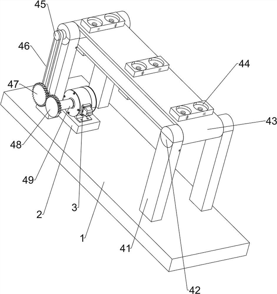
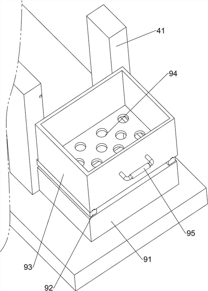
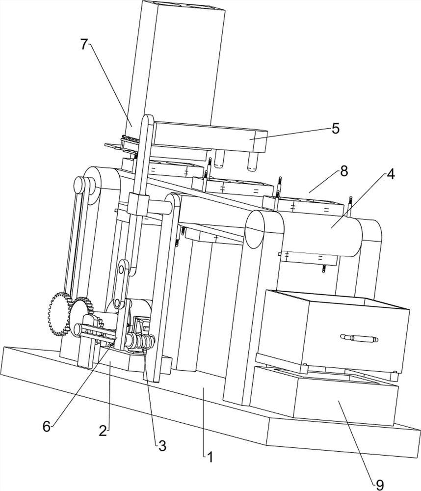
[0080] An automatic log punching device, such as figure 1 and figure 2 As shown, it includes a base 1, a support base 2, a motor 3, a transmission mechanism 4 and a punching mechanism 5. The left rear part of the base 1 is provided with a support base 2, and the top of the support base 2 is equipped with a motor 3. Transmission mechanism 4 is arranged, and transmission mechanism 4 is connected with motor 3 output shafts, and base 1 upper middle part is provided with punching mechanism 5, and punching mechanism 5 cooperates with transmission mechanism 4.
[0081] When people make logs with holes, they cannot quickly punch holes in the logs. The invention helps people to make logs with holes efficiently. Firstly, the logs are placed in the transmission mechanism 4, the motor 3 is started, and the output shaft of the motor 3 Drive the transmission mechanism 4 to run, the transmission mechanism 4 drives the log to move forward, and when the log moves to the bottom of the punchin...
Embodiment 2
[0083] On the basis of Example 1, such as figure 2 , image 3 , Figure 4 and Figure 7 As shown, the transmission mechanism 4 includes a first support column 41, a cylinder 42, a conveyor belt 43, a log placement plate 44, a first pulley 45, a first flat belt 46, a first gear 47, a half gear 48 and a power shaft 49, The first support column 41 is symmetrically arranged on the front and rear sides of the base 1, and the upper part of the first support column 41 on the left and right sides is rotatably connected with a roller 42, and a conveyor belt 43 is wound on the roller 42 on the front and rear sides. A log placement plate 44 is provided, and the left side of the first support column 41 on the left side of the rear part is rotated to be provided with a first gear 47, and the first gear 47 and the left side of the drum 42 on the rear side are all provided with a first pulley 45, The first pulley 45 on the upper and lower sides is wound with a first flat belt 46, the out...
Embodiment 3
[0088] On the basis of Example 2, such as figure 1 , Figure 4 , Figure 5 , Figure 6 and Figure 7 As shown, a reciprocating mechanism 6 is also included. The left rear portion of the base 1 is provided with a reciprocating mechanism 6. The reciprocating mechanism 6 is connected with the punching mechanism 5. The reciprocating mechanism 6 includes a third fixed column 61, a second pulley 62, a Two flat belts 63, the second gear 64, the fourth fixed column 65, the torsion spring 66, the fifth fixed column 67, the sixth fixed column 68 and the fixed plate 69, the left rear portion on the base 1 is provided with the third fixed column 61 , the upper part of the third fixed column 61 is rotatably provided with a second gear 64, the second gear 64 meshes with the half gear 48, and the left side of the second support column 51 is rotatably connected with a fourth fixed column 65 on the left side, the fourth fixed column Post 65 and second gear 64 are all provided with second b...
PUM
 Abstract
Description
Claims
Application Information
 - R&D
- Intellectual Property
- Life Sciences
- Materials
- Tech Scout
- Unparalleled Data Quality
- Higher Quality Content
- 60% Fewer Hallucinations
Browse by: Latest US Patents, China's latest patents, Technical Efficacy Thesaurus, Application Domain, Technology Topic, Popular Technical Reports.
© 2025 PatSnap. All rights reserved.Legal|Privacy policy|Modern Slavery Act Transparency Statement|Sitemap|About US| Contact US: help@patsnap.com


