
Novel electric injector

A syringe and electric technology, applied in the field of syringes, can solve the problems of low injection efficiency, low efficiency, and difficult clamping, and achieve the effects of precise control of rotation speed and number of turns, precise injection dose, and stable and consistent power

Inactive Publication Date: 2021-01-19
程国辉
View PDF7 Cites 0 Cited by
  • Summary
  • Abstract
  • Description
  • Claims
  • Application Information

AI Technical Summary

Problems solved by technology

[0002] A syringe is a common medical appliance, mainly used to extract or inject gas or liquid with a needle. The syringe can also be used for medical equipment, containers, and scientific instruments such as some chromatography to inject through a rubber septum. Veterinary syringes are used in syringes. One, but the existing veterinary syringes have the following defects: 1. Most of them are metal shells with smooth outer walls, which are not easy to clamp when injecting large doses; 2. During manual operation, the injection dose is controlled by manually adjusting the pulley. It is easy to produce large errors; 3. When injecting oily drugs or vaccines, the tightness of the piston is not easy to adjust. If the adjustment is too loose, there will be liquid leakage; if the adjustment is too tight, it will be difficult to push; 4. When performing batch injections , Ordinary syringes can only draw 20ml of medicine at a time, and need to draw medicine repeatedly, and the injection efficiency is low; 5. When changing the needle, it needs to be manually assembled and disassembled with needle holders, which is inefficient. Therefore, we propose a new type of electric syringe

Method used


Image

  • Novel electric injector
  • Novel electric injector
  • Novel electric injector

Examples


Embodiment Construction

[0016]The technical solutions in the embodiments of the present invention will be clearly and completely described below in conjunction with the accompanying drawings in the embodiments of the present invention. Obviously, the described embodiments are only a part of the embodiments of the present invention, rather than all the embodiments. Based on the embodiments of the present invention, all other embodiments obtained by those of ordinary skill in the art without creative work shall fall within the protection scope of the present invention.

[0017]In the description of the application, it should be noted that, unless otherwise clearly specified and limited, the terms "installed", "provided with", "connected", etc. should be understood in a broad sense, for example, "connected" may be a fixed connection. It can also be detachably connected or integrally connected; it can be mechanically connected or electrically connected; it can be directly connected or indirectly connected through...


PUM


Abstract

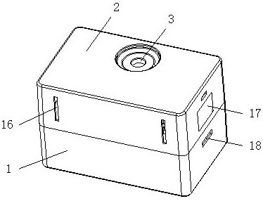
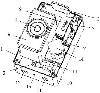
The invention discloses a novel electric injector. The novel electric injector comprises a shell, wherein a storage battery is fixedly connected to the left end of the bottom of an inner cavity of theshell, a voltage stabilizer is fixedly connected to the right end of the bottom of the inner cavity of the shell, a partition plate is fixedly connected to the lower end of the inner cavity of the shell, a liquid medicine box is fixedly connected to the top of the partition plate, and a stepping motor is fixedly mounted at the lower end of the left side of the liquid medicine box; and a peristaltic pump is connected to the driving end of the stepping motor, and a liquid medicine output hole is formed in the left side of the shell and located in the top of the partition plate. The stepping motor is driven by the storage battery, the output dosage and pressure of liquid are controlled by controlling the number of turns and the speed of the peristaltic pump driven by the stepping motor, andunder the condition that a special injection handle, a needle head and a needle head box are matched, one-man rapid batch injection operation can be achieved. The problem that an existing intensive farm needs frequent treatment and immunization is solved, and the effects of being easy to operate, saving time and labor, improving operation efficiency and reducing labor cost are achieved.

Description

Technical field[0001]The invention relates to the technical field of syringes, in particular to a new type of electric syringe.Background technique[0002]Syringe is a common medical appliance. It is mainly used to draw or inject gas or liquid with a needle. Syringe can also be used for medical equipment, containers, such as some scientific instruments in chromatography, to inject through a rubber septum. Veterinary syringes are used in syringes. One, but the existing veterinary syringes have the following defects: 1. Most of them are metal shells with smooth outer walls, which are difficult to hold when large doses are injected; 2. In manual operation, the injection dose is controlled by manual adjustment pulleys. Large errors are prone to occur; 3. When injecting oily drugs or vaccines, the tightness of the piston is not easy to adjust. If the adjustment is too loose, liquid leakage will occur, and if the adjustment is too tight, it will be difficult to push; 4. When performing batc...

Claims


Application Information

Patent Timeline
Patent Type & Authority Applications(China)
IPC IPC(8): A61D7/00A61M5/20A61M5/31A61M5/142
CPCA61D7/00A61M5/20A61M5/31A61M5/142A61M2005/2006A61M2205/3334
Inventor 程国辉
Owner 程国辉
Learn More